Light-heat conversion energy-saving technology for fluid conveying pipeline

A light-to-heat conversion and fluid transportation technology, which is applied in pipeline heating/cooling, pipeline protection, heat exchange equipment, etc., can solve the problems of high energy consumption for heating pipelines, high cost and time for maintenance and replacement, etc.

Inactive Publication Date: 2018-10-09
李能彬
View PDF4 Cites 2 Cited by
  • Summary
  • Abstract
  • Description
  • Claims
  • Application Information

AI Technical Summary

Problems solved by technology

[0003] In the prior art, auxiliary heating pipes are often used for long-distance transportation of fluids in cold regions. Heating the pipes consumes a lot of energy, and if the heating pipes are damaged midway, maintenance and replacement will require high costs and time.

Method used


Image

  • Light-heat conversion energy-saving technology for fluid conveying pipeline
  • Light-heat conversion energy-saving technology for fluid conveying pipeline

Examples


Embodiment 1

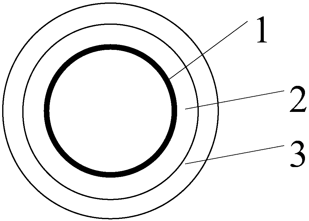
[0018] Please check figure 1 , the light-to-heat conversion energy-saving technology for fluid conveying pipelines includes an inner pipe 1, an insulation layer 2 and a light-to-heat conversion material layer 3, the heat-insulation layer 2 is set on the outer wall of the inner pipe 1 to maintain temperature; the light-to-heat conversion material layer 3 covers On the outside of the insulation layer 2, the light-to-heat conversion material layer 3 converts sunlight into heat. like figure 1 As shown, the light-to-heat conversion material layer 3 is coated on the outer side of the thermal insulation layer 2 . The material of the insulation layer 2 can be selected from at least one of polyurethane foam, phenolic foam, glass wool, rock wool and expanded perlite.

[0019] Photothermal conversion materials refer to materials that concentrate solar radiation energy by reflection, absorption or other means and convert it into a sufficiently high temperature. Photothermal conversion ...

Embodiment 2

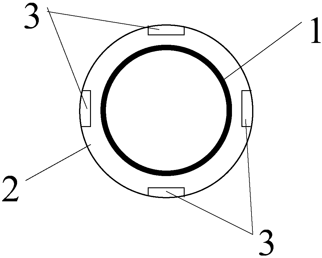
[0030] Please check figure 2 , the light-to-heat conversion energy-saving technology for fluid conveying pipelines includes an inner pipe 1, an insulation layer 2 and a light-to-heat conversion material layer 3, the heat-insulation layer 2 is set on the outer wall of the inner pipe 1 to maintain temperature; the light-to-heat conversion material layer 3 covers On the outside of the insulation layer 2, the light-to-heat conversion material layer 3 converts sunlight into heat. like figure 2 As shown, the light-to-heat conversion material layer is nested outside the insulation layer. The material of the insulation layer 2 can be selected from at least one of polyurethane foam, phenolic foam, glass wool, rock wool and expanded perlite.

[0031] When the pipeline transports fluid, the light-to-heat conversion material layer 3 covers the outer side of the insulation layer 2, and the light-to-heat conversion material layer 3 absorbs sunlight and converts sunlight into heat withou...


PUM


Abstract

The invention discloses a light-heat conversion energy-saving technology for a fluid conveying pipeline. The light-heat conversion energy-saving technology for the fluid conveying pipeline comprises an inner pipeline, an insulating layer and light-heat conversion material layers. The outer wall of the inner pipeline is sleeved with the insulating layer for heat preservation. The outer side of theinsulating layer is covered with the light-heat conversion material layers, and the light-heat conversion material layers convert sunlight into heat. According to the light-heat conversion energy-saving technology for the fluid conveying pipeline, the light-heat conversion material layers absorb sunlight and convert the sunlight into heat without auxiliary heating energy consumption, and the insulating layer can absorb the heat generated by the light-heat conversion material layers and plays an auxiliary heating role in the internal pipeline. The heat-heat conversion energy-saving technology for the fluid conveying pipeline is particularly suitable for application in the field of long-distance fluid conveying in cold regions.

Description

technical field [0001] The invention relates to the technical field of pipeline transportation, in particular to a light-to-heat conversion energy-saving technology for fluid transportation pipelines. Background technique [0002] At present, in the industry, various cold and hot fluid medium transportation pipelines such as petroleum, natural gas, and chemical raw materials are important components in petroleum, chemical, light industry, textile, metallurgy, and electric power industries, and are directly related to the long-term and safety of the industry. ,Stable operation. Most areas in northern my country are in cold regions, and effective insulation measures must be taken for long-distance pipeline transportation to prevent the fluid in the pipeline from being frozen during transportation. [0003] In the prior art, auxiliary heating pipes are often used to transport fluids over long distances in cold regions. Heating the pipes consumes a lot of energy, and if the hea...

Claims


Application Information

Patent Timeline
Patent Type & Authority Applications(China)
IPC IPC(8): F16L53/30F16L59/02
CPCF16L53/30F16L59/02
Inventor 李能彬
Owner 李能彬
Why Eureka
Try Eureka