
Method and device for sharpening image

An image sharpening and image technology, applied in the field of image processing, can solve problems such as video image quality degradation

Active Publication Date: 2018-10-09
ARKMICRO TECH
View PDF19 Cites 2 Cited by
  • Summary
  • Abstract
  • Description
  • Claims
  • Application Information

AI Technical Summary

Problems solved by technology

[0005] The purpose of the present invention is to provide a method and device for image sharpening, which aims to solve the problem that the existing image sharpening technology only considers the image information in the airspace for sharpening, and the noise is treated as details after sharpening and amplifying, resulting in poor video image quality. The overall decline in the problem

Method used


Image

  • Method and device for sharpening image
  • Method and device for sharpening image
  • Method and device for sharpening image

Examples


Embodiment 1

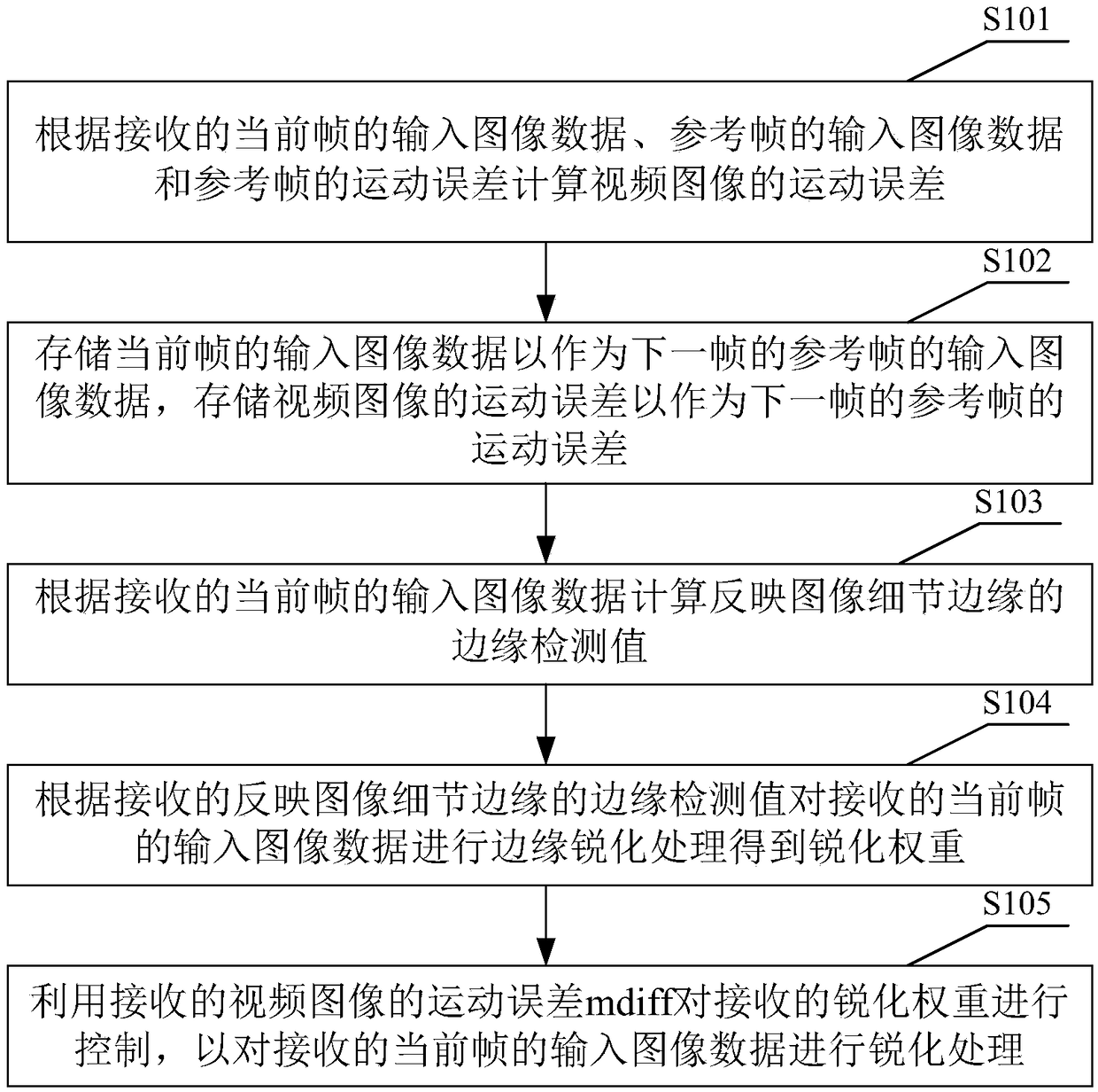
[0027] see figure 1 The image sharpening method provided by Embodiment 1 of the present invention includes the following steps:

[0028] S101. Calculate the motion error of the video image according to the received input image data of the current frame, the input image data of the reference frame, and the motion error of the reference frame.

[0029] S101 is used to judge the motion intensity of the input video, so as to control the weight of image sharpening more optimally, so as to obtain a better image sharpening effect without causing scatter points that are uncomfortable to the human eye in the moving image, resulting in a decrease in video image quality .

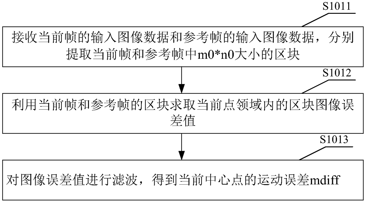
[0030] see figure 2 , S101 may specifically include the following steps:

[0031] S1011. Receive the input image data of the current frame and the input image data of the reference frame, respectively extract blocks of m0*n0 size in the current frame and the reference frame, wherein m0 and n0 are natural numbers, ...

Embodiment 2

[0071] see Figure 5 , the image sharpening device provided in Embodiment 2 of the present invention includes:

[0072] Motion error calculation module 11, for calculating the motion error of the video image according to the input image data of the received current frame, the input image data of the reference frame and the motion error of the reference frame;

[0073] The storage module 12 is used to store the input image data of the current frame as the input image data of the reference frame of the next frame, and store the motion error of the video image as the motion error of the reference frame of the next frame;

[0074] The edge detection value calculation module 13 is used to calculate the edge detection value reflecting the image detail edge according to the input image data of the received current frame;

[0075] The edge sharpening processing module 14 is used to perform edge sharpening processing on the received input image data of the current frame according to t...


PUM


Abstract

The present invention is applicable to the field of image processing and provides a method and device for sharpening an image. The method comprises a step of calculating a motion error of a video image according to input image data of a current frame, the input image data of a reference frame and a motion error of the reference frame, a step of storing the input image data of the current frame asinput image data of a reference frame of a next frame and storing the motion error of the video image as a motion error of the reference frame of a next frame, a step of calculating an edge detectionvalue reflecting an image detail edge according to the input image data of the current frame, a step of carrying out edge sharpening processing on the input image data of the received current frame according to the edge detection value to obtain a sharpening weight, and a step of controlling the received sharpening weight by using the received motion error of the video image to sharpen the input image data of the received current frame. Through the method of the invention, the motion error of the obtained video image is accurate, the sharpening of the video image is more reasonable, and at thesame time, a still image can obtain a good sharpening effect.

Description

technical field [0001] The invention belongs to the field of image processing, in particular to an image sharpening method and device. Background technique [0002] With the development of technology, the application of digital video images is becoming more and more common, and the requirements for video images are getting higher and higher in the fields of mobile devices such as cameras and mobile phones, as well as vehicle and monitoring. Video images will be mixed with various noises in the process of acquisition, transmission and imaging, and the existence of noise seriously affects the quality of video images. High-resolution, high-definition images have become a common requirement for image applications. [0003] In the process of video processing, including the generation and transmission of sensor raw image data and subsequent ISP processing, it is inevitable to cause blurring of video images. In order to make the details and edges of the image clearer and reduce t...

Claims


Application Information

Patent Timeline
IPC IPC(8): H04N5/213H04N5/14
CPCH04N5/142H04N5/213
Inventor 袁扬智刘俊秀李慧星石岭
Owner ARKMICRO TECH
Learn More