
Intelligent toothbrush

A toothbrush, intelligent technology, applied in the fields of dentistry, cleaning teeth, medical science, etc., can solve problems such as poor cleaning effect of smart toothbrush and inability to thoroughly clean the brushing experience, and achieve the effect of improving cleanliness, precise brushing, and comfortable use experience

Pending Publication Date: 2018-10-12
GUANGDONG XIAOTIANCAI TECH CO LTD
View PDF0 Cites 2 Cited by
  • Summary
  • Abstract
  • Description
  • Claims
  • Application Information

AI Technical Summary

Problems solved by technology

[0003] The purpose of the present invention is to provide a smart toothbrush, which aims to solve the technical problems that the smart toothbrush in the prior art cannot thoroughly clean and brush teeth and the experience effect is not good

Method used


Image

  • Intelligent toothbrush
  • Intelligent toothbrush
  • Intelligent toothbrush

Examples


Embodiment 1

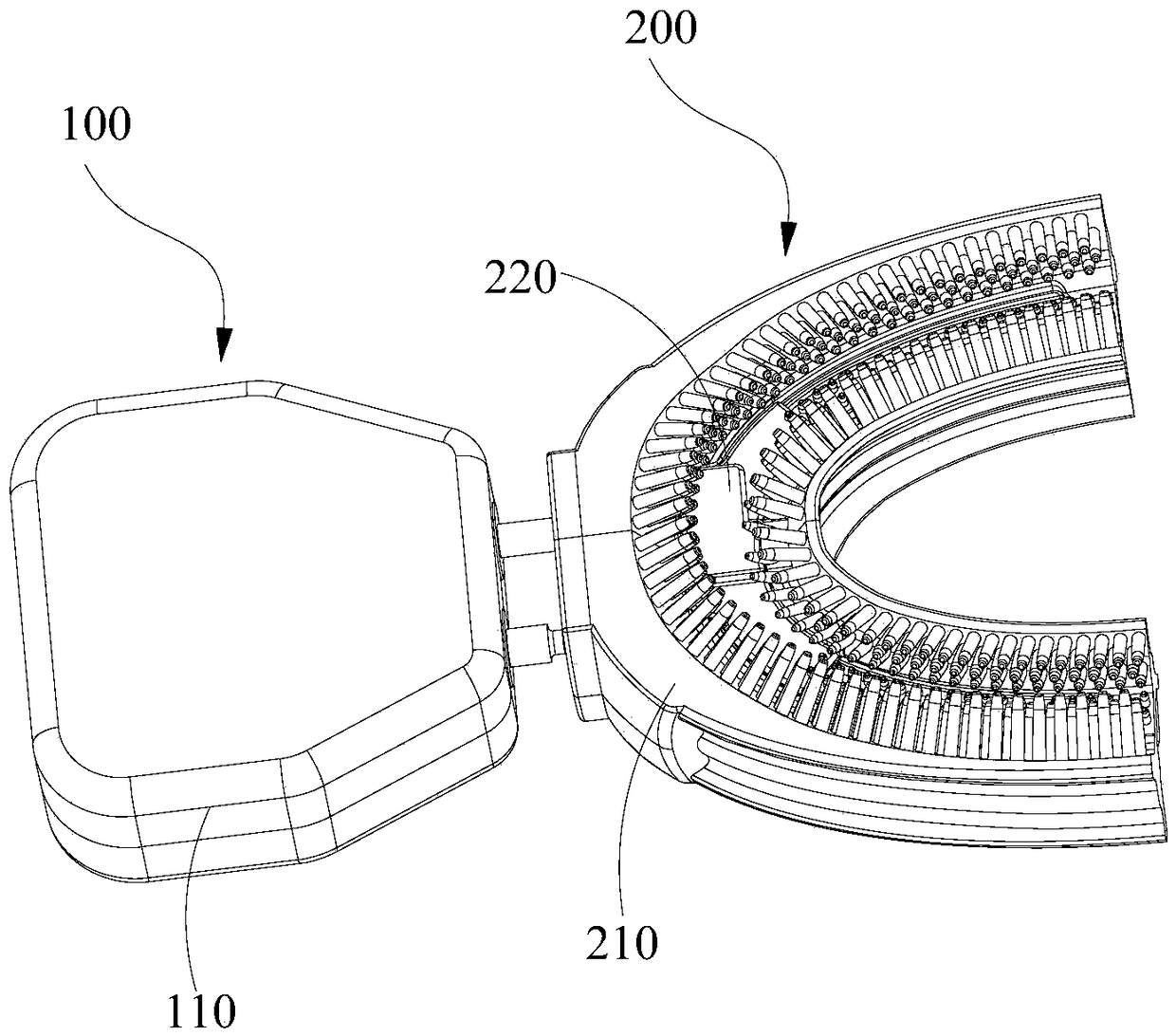
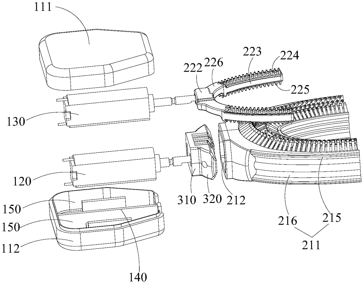
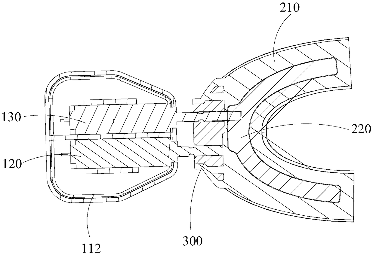
[0029] Please refer to figure 1 , The first embodiment of the present invention provides a smart toothbrush, including a host 100, a brace 200 and a control circuit (not shown in the figure). The host 100 includes a host housing 110 and a driving motor arranged in the host housing 110. The mouthpiece 200 includes a first mouthpiece 210 for cleaning inner and outer tooth surfaces, and a second mouthpiece 220 arranged in the first mouthpiece 210 and used for cleaning the molar surface. The first mouthpiece 210 is connected with the first drive shaft, and the second mouthpiece 220 is connected with The second transmission shaft is connected. In this embodiment, there are two driving motors, which are arranged in the main body housing 110. For the convenience of description, the first driving motor 120 and the second driving motor 130 are named here. The first transmission shaft and the second transmission shaft are the output shaft of the first drive motor 120 and the output shaf...

Embodiment 2

[0044] In the present invention, a smart toothbrush (not shown) is also provided. The difference from the first embodiment is that the drive motor is a drive motor. The output shaft of the drive motor is provided with a transmission structure. The transmission structure is different from the first transmission. The shaft is fixedly connected with the second transmission shaft. Through the combination of a driving motor and a transmission structure, it is also possible to drive two transmission shafts separately or simultaneously to drive the two braces to work. Specifically, the transmission structure is a commonly used transmission structure in the prior art, and will not be repeated here. What is not described in this embodiment is the same as the embodiment, and will not be repeated here.


PUM


Abstract

The invention relates to the technical field of toiletries, and provides an intelligent toothbrush. The intelligent toothbrush comprises a main machine, a tooth socket and a control circuit, wherein the main machine comprises a main machine shell and a driving motor arranged in the main machine shell; the tooth socket comprises a first tooth socket used for cleaning inner and outer tooth surfacesand a second tooth socket arranged in the first tooth socket and used for cleaning molar surfaces; the first tooth socket is connected with a first transmission shaft, and the second tooth socket is connected with a second transmission shaft; the first transmission shaft is in transmission connection with the second transmission shaft and the driving motor; and the control circuit is electricallyconnected with the driving motor to drive the first transmission shaft and the second transmission shaft correspondingly to drive the first tooth socket and the second tooth socket to move, and to drive the first transmission shaft and the second transmission shaft simultaneously to drive the first tooth socket and the second tooth socket to move. According to the intelligent toothbrush, the two tooth sockets are arranged separately, so that the vibration volume of each tooth socket is reduced, and the vibration quantity and the swing quantity of each tooth socket are doubly guaranteed by a separate drive mode, so that teeth can be cleaned more thoroughly.

Description

Technical field [0001] The invention relates to the technical field of toiletries, and in particular provides a smart toothbrush. Background technique [0002] Smart toothbrushes currently on the market are mainly designed with a single motor, and are divided according to the brush head. There are two main types: traditional brush heads and braces. Traditional brush heads are similar to traditional toothbrushes. The way of brushing teeth is also similar. You need to brush your teeth by hand. The difference is that the brush head of this type of toothbrush is vibrating or swinging. This type of smart toothbrush technology has been relatively mature. The experience and effects are also very good, and it is currently the mainstream type of smart toothbrush. The smart toothbrush with braces, also called "lazy" toothbrush, is a product that has only recently appeared. Users only need to put the braces in the mouth, bite the braces, and they can automatically finish brushing their tee...

Claims


Application Information

Patent Timeline
IPC IPC(8): A61C17/34
CPCA61C17/221A61C17/222A61C17/34
Inventor 周卫国
Owner GUANGDONG XIAOTIANCAI TECH CO LTD
Learn More