Auxiliary device for medical rehabilitation

An auxiliary device, U-shaped technology, applied in the direction of elastic resistance devices, massage auxiliary products, physical therapy, etc., can solve the problems of high cost, small use range, single function, etc., to facilitate disassembly and installation, promote blood circulation, good effect

Inactive Publication Date: 2018-10-12
陈佳康
View PDF0 Cites 3 Cited by
  • Summary
  • Abstract
  • Description
  • Claims
  • Application Information

AI Technical Summary

Problems solved by technology

[0004] The purpose of the present invention is to provide an auxiliary device for medical rehabilitation to solve the problem that the existing auxiliary device for medical rehabilitation proposed in the abo

Method used


Image

  • Auxiliary device for medical rehabilitation
  • Auxiliary device for medical rehabilitation
  • Auxiliary device for medical rehabilitation

Examples


Embodiment 1

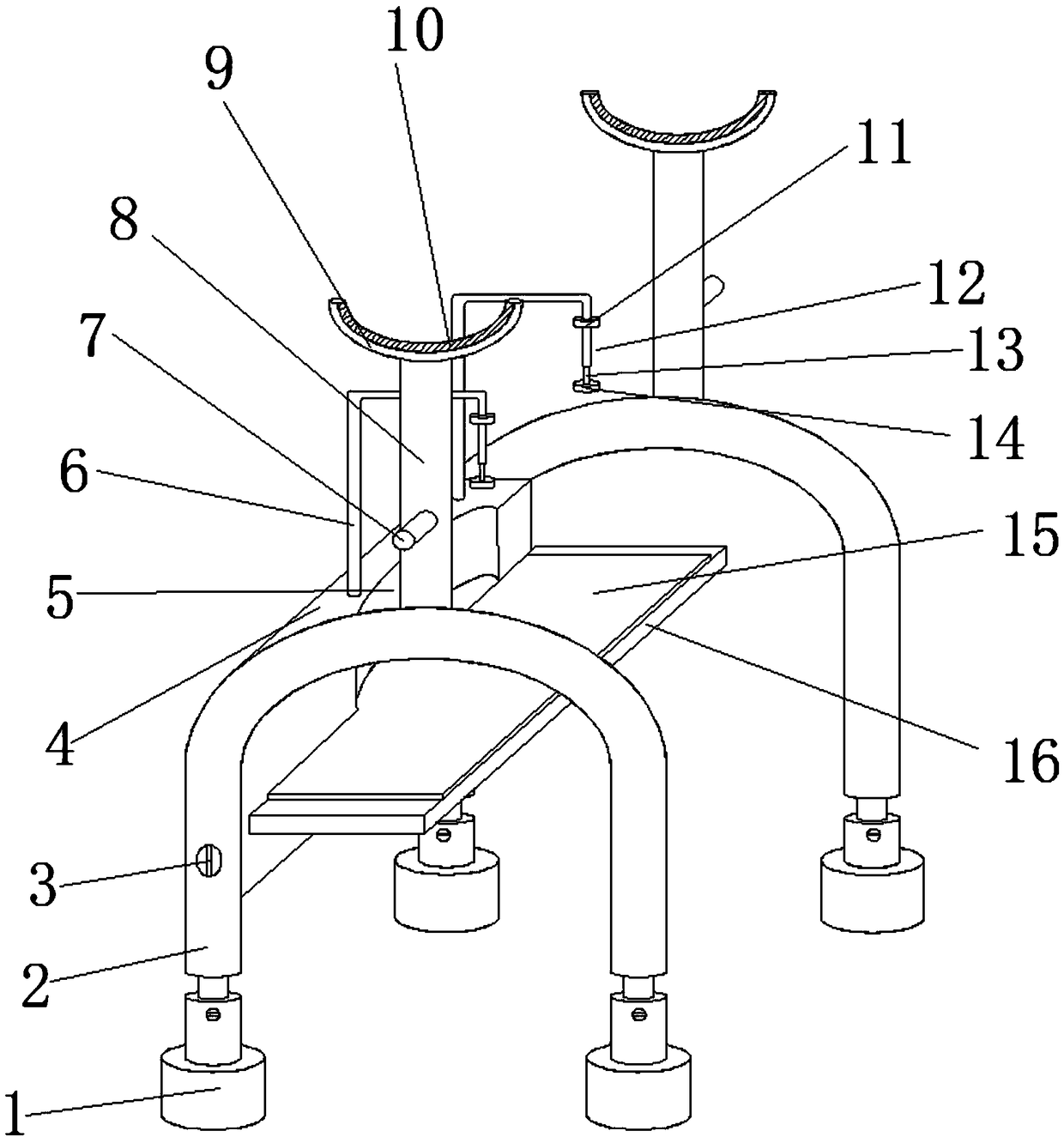
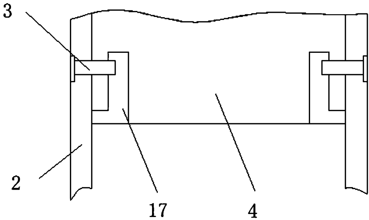
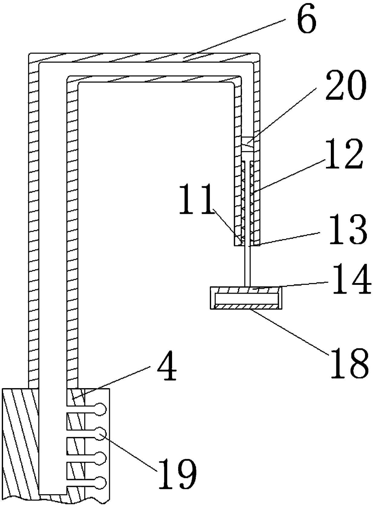
[0022] see Figure 1-4 , this embodiment provides an auxiliary device for medical rehabilitation, including four non-slip foot pads 1, two inverted U-shaped brackets 2, two pillars 8 and an arc-shaped bracket 9 installed on the pillars 8, four anti-skid The foot pads 1 are respectively installed on the lower ends of the two inverted U-shaped brackets 2. The outer walls of the two pillars 8 are provided with handrails 7. A backing plate 4 is inserted in common on the bar 17, and the inverted U-shaped support 2 fixes the L-shaped inserting rod 17 and the backing plate 4 through the bolt 3, and the seat plate 16 with the seat cushion 15 is fixedly installed on the right end of the backing plate 4. The surface of the plate 4 is provided with an arc groove 5, and the inner wall of the arc groove 5 is plugged with two rows of elastic air bags 19, and two air guide tubes 6 are installed on the upper end of the plate 4, and the inner cavity of the air guide tube 6 and the inner cavity...

Embodiment 2

[0025] see figure 1 , On the basis of Embodiment 1, a further improvement is made: the upper surface of the arc-shaped bracket 9 is pasted with an arc-shaped soft pad 10 by Velcro. In this solution, the curved cushion 10 can improve the comfort of the patient.

[0026] Wherein, the connection mode between the curved cushion 10 and the curved bracket 9 is not limited, it may be a fixed connection or a socket connection. In a preferred embodiment, Velcro is used for connection. In this solution, it is convenient to disassemble, clean or replace the curved cushion 10, and it is convenient to use.

Embodiment 3

[0028] see figure 1 with figure 2 , On the basis of Embodiment 1, a further improvement is made: the inverted U-shaped bracket 2 is a telescopic bracket, and the height can be adjusted according to patients of different heights. The cross section of the L-shaped inserting rod 17 is square. The stabilization effect is good. The handle 18 is a cylindrical structure, and the annular side is processed with anti-slip lines, which is convenient for the patient to hold and has a good anti-slip effect. The pillar 8 is installed in the middle position of the upper end of the inverted U-shaped bracket 2, and the two are connected by welding. Installed in the middle of the upper end, when the patient is in use, the overall stability is high, connected by welding, the connection is firm, stable and easy to use. Both the inverted U-shaped bracket 2 and the pillar 8 are hollow structures. This design reduces the overall weight, facilitates handling, and saves materials at the same tim...


PUM


Abstract

The invention discloses an auxiliary device for medical rehabilitation. The auxiliary device for medical rehabilitation comprises four anti-slip foot pads, two inverted U-shaped supports, two supporting columns and an arc-shaped bracket installed on the supporting columns, wherein the four anti-slip foot pads are correspondingly installed at the lower ends of the two inverted U-shaped supports, L-shaped insertion rods are installed on the front and back inner walls of the two inverted U-shaped supports, one leaning plate is insert-connected to the two L-shaped insertion rods, the inverted U-shaped supports fix the L-shaped insertion rods and the leaning plate through bolts, a seat plate with a seat cushion is fixedly installed at the right end of the leaning plate, arc-shaped grooves are formed in the leaning plate, two rows of elastic air bags are insert-connected to the inner walls of the arc-shaped grooves, two air guiding pipes are installed at the upper end of the leaning plate, pistons are movably installed in the air guiding pipes, T-shaped pull rods are connected to the lower ends of the pistons, and limiting rings re embedded and installed at lower-end openings of the airguiding pipes. The auxiliary device for medical rehabilitation can make a patient exercise arm muscles by himself/herself, while can massage the waist and can be used in a dismounted and split way.

Description

technical field [0001] The invention relates to the technical field of auxiliary devices for medical rehabilitation, in particular to an auxiliary device for medical rehabilitation. Background technique [0002] Auxiliary devices for medical rehabilitation are used to better help patients recover and improve the treatment effect on patients. [0003] The existing auxiliary devices for medical rehabilitation are poor in use effect. Usually, they are electrical machinery to help patients exercise. small. Contents of the invention [0004] The purpose of the present invention is to provide an auxiliary device for medical rehabilitation to solve the problem that the existing auxiliary device for medical rehabilitation proposed in the background technology has a single function. Generally, an auxiliary device can only perform training and treatment on one part of the body. And the cost is high, and the problem of using range is small. [0005] In order to achieve the above o...

Claims


Application Information

Patent Timeline
IPC IPC(8): A61H3/00A61H7/00A63B21/02A63B23/12
CPCA61H3/00A61H7/001A61H2201/1261A61H2205/081A63B21/02A63B23/12
Inventor 陈佳康
Owner 陈佳康
Why Eureka
Try Eureka