
Semi-continuous casting device for long slabs of large-scale magnesium alloys

A magnesium alloy, large-scale technology, applied in the field of magnesium alloy casting, can solve problems such as cold cracking and hot cracking, achieve the effects of reducing cracking tendency, reducing temperature gradient, and prolonging service life

Active Publication Date: 2019-12-24
NORTHEASTERN UNIV LIAONING
View PDF14 Cites 0 Cited by
  • Summary
  • Abstract
  • Description
  • Claims
  • Application Information

AI Technical Summary

Problems solved by technology

[0004] In addition to the above-mentioned problems, large-scale ingots, especially for magnesium alloy ingots with a rectangular cross-section (including flat ingots or square ingots) with a symmetrical structure, due to the cooling rate and cooling sequence in the circumferential and width directions during the casting process Casting stress and strain caused by different factors often lead to hot cracking during solidification or cold cracking after solidification

Method used


Image

  • Semi-continuous casting device for long slabs of large-scale magnesium alloys
  • Semi-continuous casting device for long slabs of large-scale magnesium alloys
  • Semi-continuous casting device for long slabs of large-scale magnesium alloys

Examples


Embodiment 1

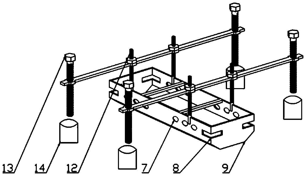
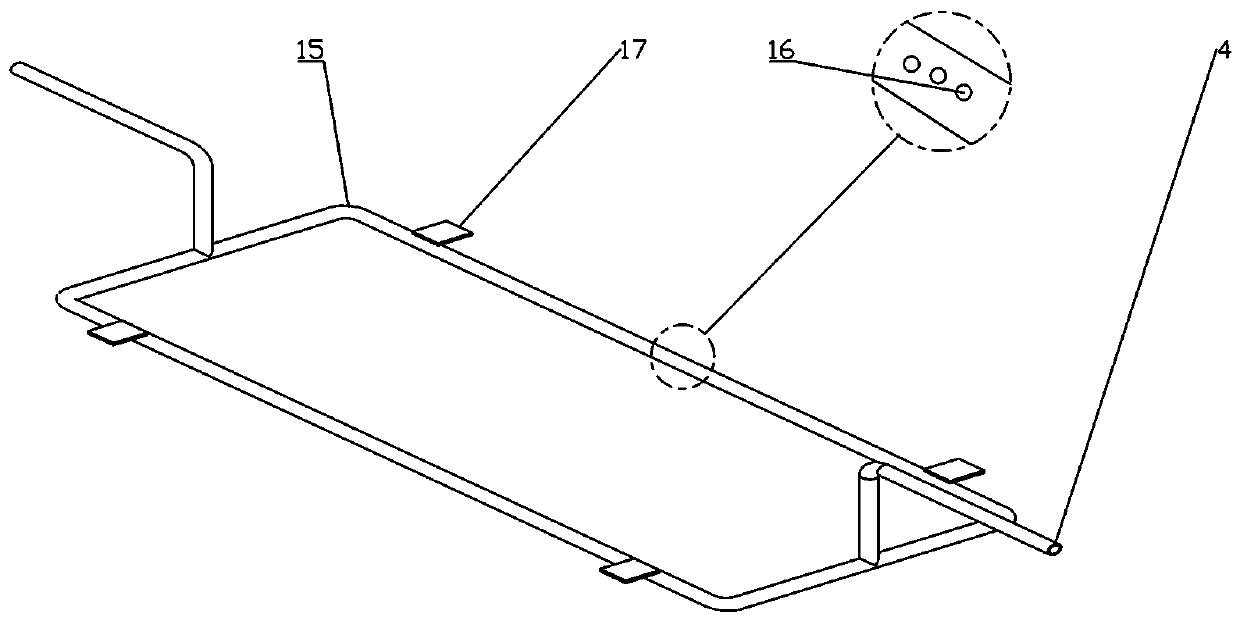
[0049] The structure of the semi-continuous casting device for long slabs of large-size magnesium alloys is as follows: figure 1 As shown, it includes a diverter plate, a crystallizer and a dummy head 6; the crystallizer includes a mold inner sleeve 26, an electromagnetic coil 5, a cold water tank 31 and an oil cover plate 24, and a gas protection nozzle 3 is arranged above the oil cover plate 24 , the crystallizer inner sleeve 26 is provided outside, the electromagnetic coil 5 is located between a cold water tank 31 and the crystallizer inner sleeve 26; the top of the crystallizer inner sleeve 26 is a shunt plate, and the lower part of the crystallizer inner sleeve 26 is a dummy head 6;

[0050] The diverter plate is a single diverter plate 1, such as figure 2 As shown, a height adjustment device is arranged above the diverter plate, and the height adjustment device is composed of a height adjustment screw fixing base 14, a height adjustment screw 13 and a diverter plate sup...

Embodiment 2

[0065] Device structure is the same as embodiment 1, and difference is:

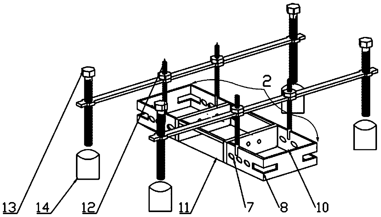
[0066] The diverter plate is split type diverter plate 2, the structure is as follows image 3 As shown, the split type diverter plate 2 is fixedly connected together by two square grooves 10 through a fixed support base plate 11, and the tops of each square groove 10 are fixedly connected together by connecting rods. The part of the corner is provided with a rectangular shunt opening 8, and a circular shunt hole 7 is arranged on the side wall of the square groove 10; several small holes are arranged on the side wall adjacent to one square groove and the other square groove;

[0067] The method is the same as in Example 1; the obtained magnesium alloy large-size ingot product has no cracks.


PUM

PropertyMeasurementUnit
diameteraaaaaaaaaa
thicknessaaaaaaaaaa
widthaaaaaaaaaa

Abstract

The invention discloses a large-gauge magnesium alloy long and flat ingot semicontinuous casting device. The large-gauge magnesium alloy long and flat ingot semicontinuous casting device comprises a distribution disk, a crystallizer and a dummy bar head. A height adjustment device is arranged above the distribution disk. The distribution disk is a monomer type distribution disk or a split type distribution disk. The monomer type distribution disk is of an integral structure formed by a rectangular side wall and a trapezoid bottom groove. One rectangular distribution port is arranged in each corner of the side wall. The split type distribution disk is formed by a plurality of rectangular grooves through a fixing supporting base plate in a fixedly connected manner, and is provided with rectangular distribution ports in the corners. A third cold water tank is arranged below a first cold water tank. The interior of a square groove above the dummy bar head is of a stepped two-layer groove type structure. A cavity is formed inside a base of the dummy bar head. The large-gauge magnesium alloy long and flat ingot semicontinuous casting device can be used for producing and preparing magnesium alloy flat ingots of various dimensions and specifications and with stable quality, and the tearing tendency of the ingots is effectively reduced.

Description

technical field [0001] The invention belongs to the technical field of magnesium alloy casting, and in particular relates to a semi-continuous casting device for a long flat ingot of a large-scale magnesium alloy. Background technique [0002] The semi-continuous casting process, also known as Direct Chilling, is a process in which the metal melt is continuously and stably solidified into an ingot through a crystallizer. The crystallizer is mainly composed of an inner sleeve, a cooling water tank, and a water spray hole. The melt is in contact with the inner wall of the crystallizer to achieve primary cooling, and after exiting the crystallizer, the secondary cooling water is sprayed to the surface of the ingot at a certain angle through the water spray hole to achieve chilling. With the continuous improvement of industrial performance requirements for large-scale deformed structural materials, it is particularly important to produce large-scale high-quality cast slabs as h...

Claims


Application Information

Patent Timeline
Patent Type & Authority Patents(China)
IPC IPC(8): B22D11/14B22D11/08B22D11/103B22D11/124
CPCB22D11/083B22D11/103B22D11/124B22D11/14
Inventor 乐启炽侯建廖启宇贾永辉宝磊王彤
Owner NORTHEASTERN UNIV LIAONING
Learn More