Turbine airfoil with near wall multi-serpentine cooling channels

a technology of turbine airfoil and cooling channel, which is applied in the direction of liquid fuel engines, vessel construction, marine propulsion, etc., can solve problems such as the likelihood of failure, and achieve the effects of reducing the thickness of the outer wall, increasing the design flexibility, and increasing the growth potential of cooling design

Inactive Publication Date: 2009-05-19
SIEMENS ENERGY INC
View PDF17 Cites 31 Cited by
  • Summary
  • Abstract
  • Description
  • Claims
  • Application Information

AI Technical Summary

Benefits of technology

[0008]An advantage of this invention is the suction side and pressure side serpentine cooling chambers in the outer wall of the hollow airfoil may be sized and shaped appropriately to account for localized pressures and heat loads to more effectively use available cooling fluids.
[0015]Another advantage of this invention is that cooling fluids are first sent through the first and second suction side and pressure side serpentine cooling chambers and then passed to the mid-chord cooling fluid collection chambers, thereby reducing the temperature gradient in the airfoil between the outer surfaces of the airfoil and the inner aspects.

Problems solved by technology

In addition, turbine vanes and blades often contain cooling systems for prolonging the life of the vanes and blades and reducing the likelihood of failure as a result of excessive temperatures.

Method used


Image

  • Turbine airfoil with near wall multi-serpentine cooling channels
  • Turbine airfoil with near wall multi-serpentine cooling channels
  • Turbine airfoil with near wall multi-serpentine cooling channels

Examples


Embodiment Construction

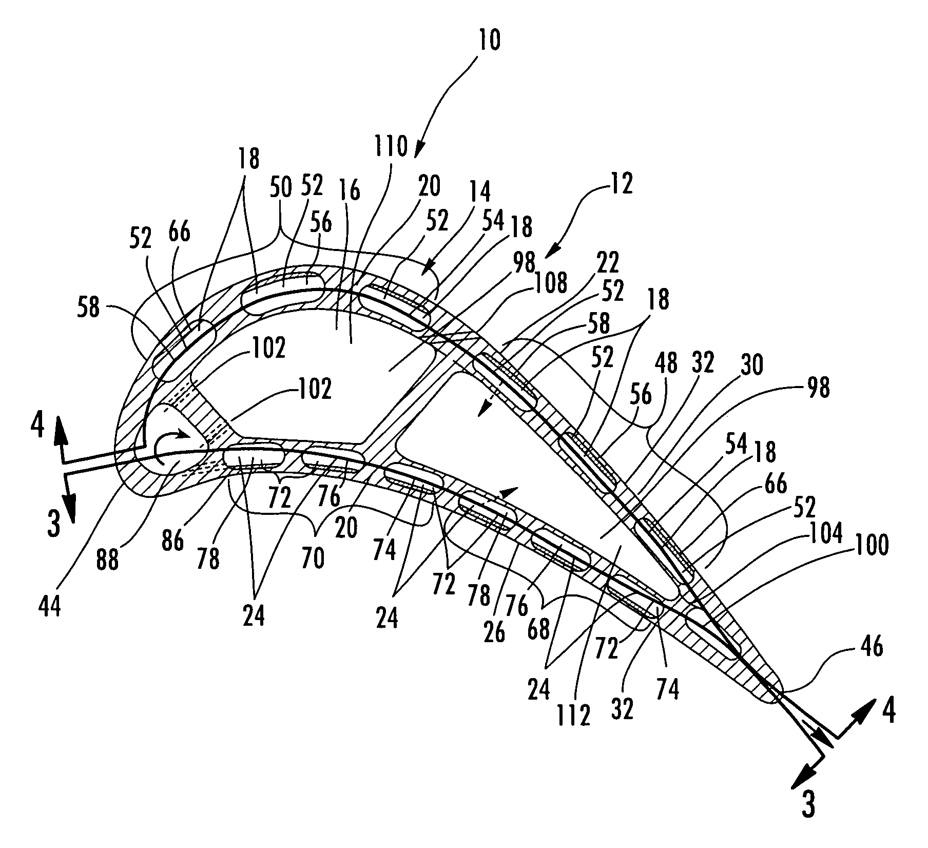
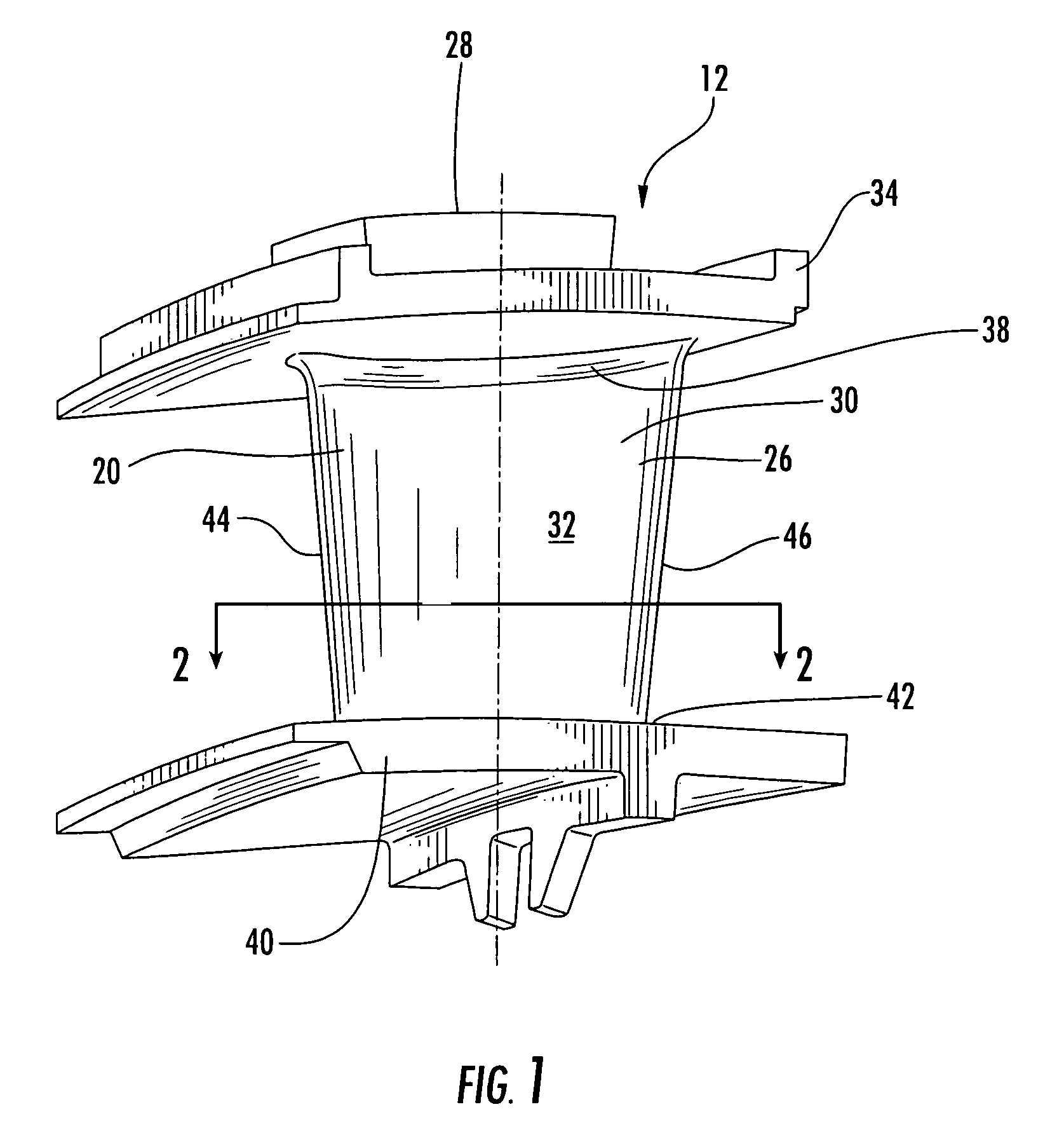
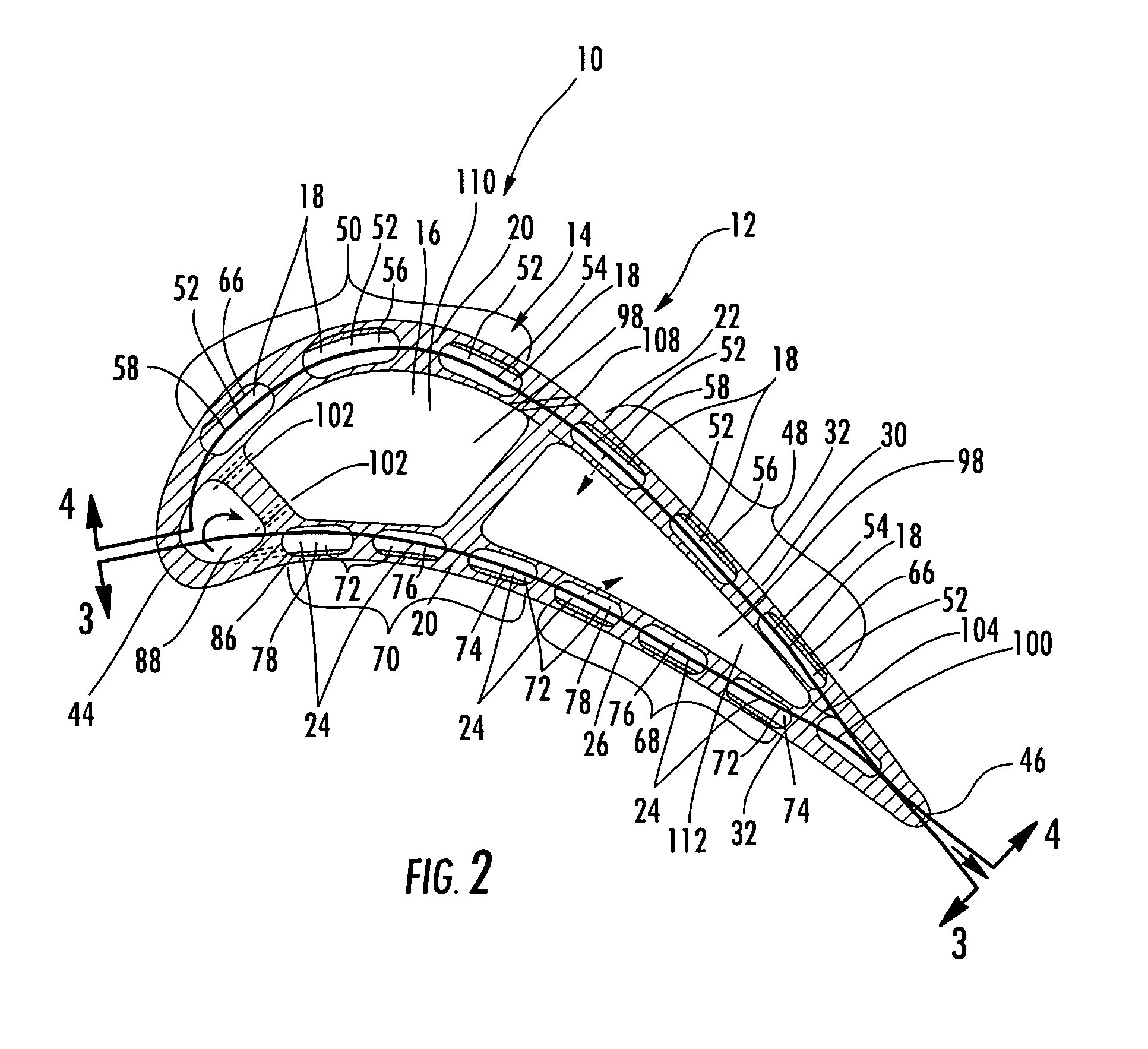
[0023]As shown in FIGS. 1-4, this invention is directed to a turbine airfoil cooling system 10 configured to cooling internal and external aspects of a turbine airfoil 12 usable in a turbine engine. In at least one embodiment, the turbine airfoil cooling system 10 may be configured to be included within a stationary turbine vane, as shown in FIGS. 1-4. While the description below focuses on a cooling system 14 in a turbine vane 12, the cooling system 10 may also be adapted to be used in a turbine blade. The turbine airfoil cooling system 10 may be formed from a cooling system 14 having a plurality of cooling channels 16. For instance, the cooling channels 16 may include one or more suction side serpentine cooling channels 18 positioned in an outer wall 20 forming a suction side 22 of the turbine airfoil 12 and may include one or more pressure side serpentine cooling channels 24 positioned in an outer wall 20 forming a pressure side 26 of the turbine airfoil 12. The cooling system 14...


PUM


Abstract

A turbine airfoil usable in a turbine engine and having at least one cooling system. At least a portion of the cooling system may be positioned in an outer wall of the turbine airfoil and be formed from at least one suction side serpentine cooling chamber and at least one pressure side serpentine cooling chamber. Each of the suction and pressure side serpentine cooling channels may receive cooling fluids from a cooling fluid supply source first before being passed through other components of the cooling system. The cooling fluids may then be passed into a mid-chord cooling chamber to cool internal aspects of the turbine airfoil, yet prevent creation of a large temperature gradient between outer surfaces of the turbine airfoil and inner aspects.

Description

FIELD OF THE INVENTION[0001]This invention is directed generally to turbine airfoils, and more particularly to hollow turbine airfoils having cooling channels for passing fluids, such as air, to cool the airfoils.BACKGROUND[0002]Typically, gas turbine engines include a compressor for compressing air, a combustor for mixing the compressed air with fuel and igniting the mixture, and a turbine blade assembly for producing power. Combustors often operate at high temperatures that may exceed 2,500 degrees Fahrenheit. Typical turbine combustor configurations expose turbine vane and blade assemblies to these high temperatures. As a result, turbine vanes and blades must be made of materials capable of withstanding such high temperatures. In addition, turbine vanes and blades often contain cooling systems for prolonging the life of the vanes and blades and reducing the likelihood of failure as a result of excessive temperatures.[0003]Typically, turbine vanes are formed from an elongated port...

Claims


Application Information

Patent Timeline
Patent Type & Authority Patents(United States)
IPC IPC(8): F01D5/08F01D5/18
CPCF01D5/186F01D5/187F05D2250/185F05D2260/202F05D2240/127
Inventor LIANG, GEORGE
Owner SIEMENS ENERGY INC
Why Eureka
Try Eureka