
Metallic 3D printer

A 3D printer and metal technology, applied in the direction of additive processing, can solve the problems of difficult popularization, high quasi-access, high cost, etc., and achieve the effect of reducing its own weight, simple structure, and cost saving

Active Publication Date: 2018-10-12
湖南西交智造科技有限公司
View PDF9 Cites 1 Cited by
  • Summary
  • Abstract
  • Description
  • Claims
  • Application Information

AI Technical Summary

Problems solved by technology

However, the common metal 3D printer system and structure are complicated, expensive, and the material powder is also expensive. It is difficult for ordinary developers to use metal printing. Therefore, the current metal 3D printers have high access to the market and are difficult to popularize.

Method used


Image

  • Metallic 3D printer
  • Metallic 3D printer
  • Metallic 3D printer

Examples


Embodiment 1

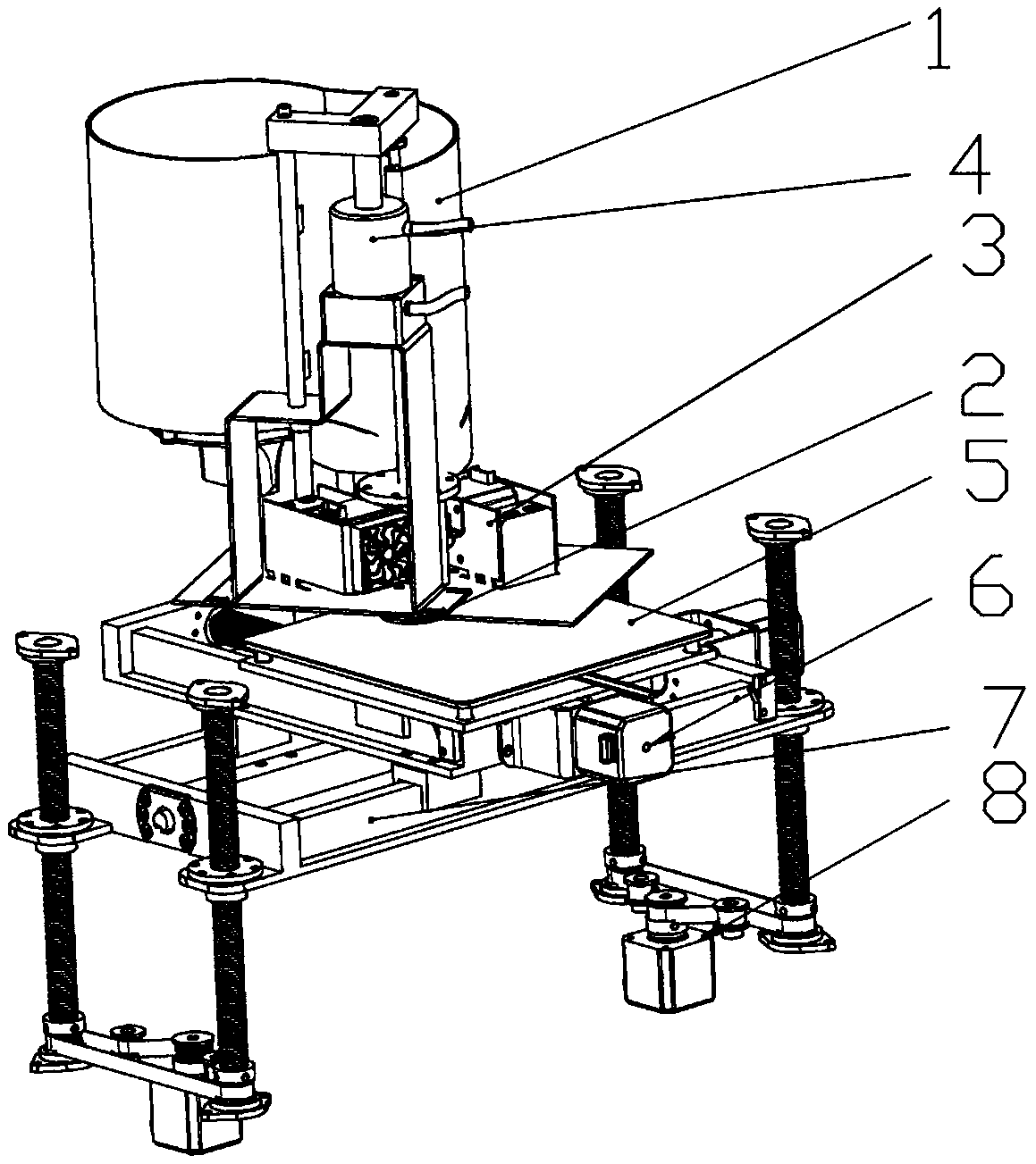
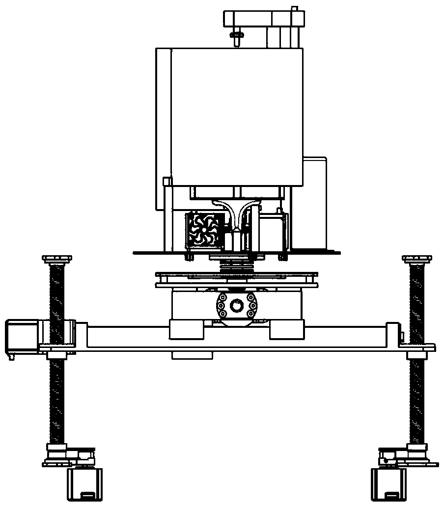
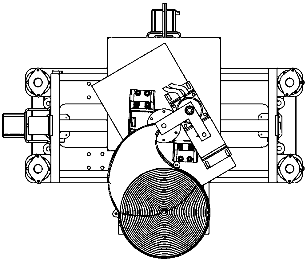
[0030] Such as figure 1 As shown in the three-dimensional structure diagram of a metal 3D printer, a metal 3D printer includes a charging assembly 1, a printing head assembly 2 is installed on the lower side of the charging assembly 1, and an extruder assembly 3 is arranged on the printing head 2 , the extruder assembly 3 cylinder assembly 4, the charging assembly 1 print head assembly 2 extruder assembly 3 cylinder assembly 4 runs through the connecting wire material rod 11, the print head assembly 2 is placed under the printing platform assembly 5, the The printing platform assembly 5 is installed on the Y-axis assembly 6 , the Y-axis assembly 6 is installed on the X-axis assembly 7 , and the X-axis assembly 7 is installed on the Z-axis assembly 8 .

[0031] Such as Figure 4 A material barrel 9 is installed in the charging assembly 1, a coil spring power assembly 12 is arranged under the material barrel 9, a coil spring knob 11 is connected under the coil spring shaft 8, a...


PUM


Abstract

The invention mainly relates to a metallic 3D printer, and belongs to the field of 3D printer equipment. According to the metallic 3D printer provided by the invention, an X-axis and a Y-axis are integrally mounted by adopting guide rail sliding blocks, so that self-weight can be reduced while the precision in a printing process is ensured at the same time; and a way of double motors and four setsof ball bearing lead screws adopted by a Z-axis is the first creation of the metallic 3D printer, so that firmness of the Z-axis in ascending and descending processes is ensured. A printing head assembly can be used for adjusting a temperature according to the types of practically-used wires; by adopting a way of automatically feeding by utilizing a coil spring, power of a feeding rod of a material barrel is provided; by adopting a double-motor spring pre-compaction device, blocking of the materials of a gear in a wire feeding process can be avoided; due to a rotary clamping air cylinder, admittance and propelling force of a material rod in a material rod supplementing process are provided; and due to arrangement of winding wires and a gas pipe and mass use of wear-resistant heat-insulation materials in a printing head device, guarantee is provided for ultrahigh-temperature and quick heating, temperature reduction and heat insulation in a metal printing process.

Description

technical field [0001] The invention belongs to the field of 3D printer equipment, and mainly relates to a metal 3D printer. technical background [0002] As a kind of rapid prototyping technology, 3D printing is a technology based on digital model files and using bondable materials such as powdered metal or plastic to construct objects by layer-by-layer printing. [0003] 3D printing is usually achieved using digital technology material printers. It is often used to make models in the fields of mold manufacturing and industrial design, and is gradually used in the direct manufacture of some products. There are already parts printed using this technology. Because 3D printing technology can quickly produce high-end customized products, and can generate almost arbitrarily complex parts without molds and tools, it greatly improves production efficiency and manufacturing flexibility. As a result, 3D printing technology has applications in jewelry, footwear, industrial design, ...

Claims


Application Information

Patent Timeline
Patent Type & Authority Applications(China)
IPC IPC(8): B22F3/115B33Y30/00
CPCB22F3/003B22F3/115B33Y30/00
Inventor 谭振国刘林林
Owner 湖南西交智造科技有限公司
Learn More