
Stable safety device for locating and cutting for steel bar production

A technology for positioning cutting and safety devices, which is applied to shearing devices, accessories of shearing machines, maintenance and safety accessories, etc., can solve problems such as easy occurrence of staff, safety accidents, and decrease in safety factor of devices, and achieve the effect of positioning work. Excellent, improve safety factor, not easy to splash around

Inactive Publication Date: 2018-10-12
丽水市莲都区君正模具厂
View PDF0 Cites 1 Cited by
  • Summary
  • Abstract
  • Description
  • Claims
  • Application Information

AI Technical Summary

Problems solved by technology

[0004] The purpose of the present invention is to provide a stable safety device for positioning and cutting steel bar production, so as to solve the problem that the stability of the existing stable safety device proposed in the above-mentioned background technology is not enough when the steel bar is used for production and cutting work. , so that the working effect of the device is not good, and when the device is in the production of steel bars, it is easy to cause safety accidents for the staff, resulting in the problem that the safety factor of the device decreases

Method used


Image

  • Stable safety device for locating and cutting for steel bar production
  • Stable safety device for locating and cutting for steel bar production
  • Stable safety device for locating and cutting for steel bar production

Examples


Embodiment Construction

[0026] The following will clearly and completely describe the technical solutions in the embodiments of the present invention with reference to the accompanying drawings in the embodiments of the present invention. Obviously, the described embodiments are only some, not all, embodiments of the present invention. Based on the embodiments of the present invention, all other embodiments obtained by persons of ordinary skill in the art without making creative efforts belong to the protection scope of the present invention.

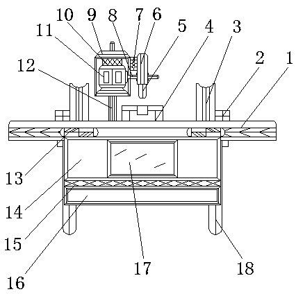
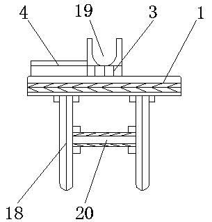
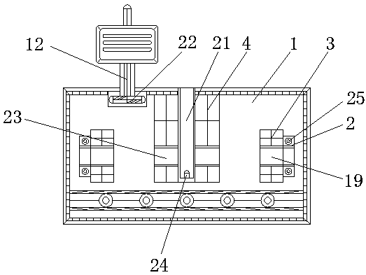
[0027] see Figure 1-5 , the present invention provides a technical solution: a stable safety device for positioning and cutting steel bar production, including a workbench 1, a fixed block 2, a support block 3, a placement block 4, a blade 5, a chip cover 6, and a connecting block 7 , shaft 8, box 9, shock absorber 10, motor 11, movable rod 12, rotating shaft 13, main baffle 14, connecting strip 15, auxiliary baffle 16, observation window 17, support rod 18, ...


PUM

PropertyMeasurementUnit
heightaaaaaaaaaa

Abstract

The invention relates to a stable safety device for locating and cutting for steel bar production. The stable safety device comprises a working table, a main baffle and supporting rods. Fixed blocks are arranged at the top of the working table, and a supporting block is arranged at the position, close to the center axis of the working table, of the inner side of each fixed block. A threaded hole is formed in each fixed block. A containing block is fixed to the top end of the working table, and a rotary shaft is arranged on the outer side of the working table. The main baffle is movably arranged at the bottom end of the rotary shaft, and an observation window is mounted on the inner side of the main baffle. The bottom of the main baffle is connected with a connecting strip. The stable safety device has the advantages that through the arrangement of a blade, a chip blocking cover, a box body, a moving rod, a moving shaft and the working table, the moving rod and the working table form amoving structure through the moving shaft, when cutting work needs to be carried out on steel bars, workers can move the box body by grabbing the moving rod through the rotating function of the movingshaft, and the blade is driven to carry out cutting work on the steel bars.

Description

technical field [0001] The invention relates to the technical field of steel bar production, in particular to a stable safety device for positioning and cutting for steel bar production. Background technique [0002] With the development of science and technology and the progress of the social era, the production and processing equipment of steel bars is becoming more and more advanced. When the steel bars are produced through the stable safety device of positioning and cutting, it can be accurately positioned and the safety factor of the staff when operating is improved. It speeds up the work efficiency of the enterprise and maximizes the interests of the enterprise. [0003] During the use of the existing stable safety device, the stability of the production and cutting of the steel bar is not enough, so that the working effect of the device is not good, and the safety accident of the staff is prone to occur when the device is in the production of the steel bar, causing th...

Claims


Application Information

Patent Timeline
Patent Type & Authority Applications(China)
IPC IPC(8): B23D19/00B23Q11/08B23D33/02B23Q11/00
CPCB23D19/00B23D33/02B23Q11/005B23Q11/08
Inventor 张群
Owner 丽水市莲都区君正模具厂
Learn More