Feeding device for plate splicing welding

A technology of plate and jacking devices, which is applied in the direction of auxiliary devices, welding equipment, auxiliary welding equipment, etc., can solve the problems of time-consuming and labor-consuming, low welding seam adjustment accuracy, low efficiency, etc., so as to save the time of manual adjustment , Improve welding efficiency and low production cost

Inactive Publication Date: 2018-10-12
WUHU JUNRU THERMAL INSULATION MATERIAL CO LTD
View PDF3 Cites 1 Cited by
  • Summary
  • Abstract
  • Description
  • Claims
  • Application Information

AI Technical Summary

Problems solved by technology

[0002] The raw material of the water tank is stainless steel plate, which is rolled and welded into the cylinder of the water tank, and the circular cover and the bottom of the water tank are cut from the plate, and welded to both ends of the cylinder to obtain a circular water tank. The plate in the factory The width of the roll is fixed. For the water tank whose height is greater than the width of the coil, it is necessary to splice multiple plates and then roll them into a cylinder. Set up transport rollers at both ends of the splicing machine, and separate the two spliced ​​plates from the two ends. The transport roller is pushed to the joint of the jigsaw machine, and the worker uses the pry bar to adjust the position of the two plates, so that the two ends of the two plates are aligned and kept parallel to each other without inclination, so as to ensure that the welds between the plates are of the same size. Manual operation is time-consuming and labor-intensive, with low efficiency and low accuracy of weld adjustment

Method used


Image

  • Feeding device for plate splicing welding
  • Feeding device for plate splicing welding
  • Feeding device for plate splicing welding

Examples


specific Embodiment approach

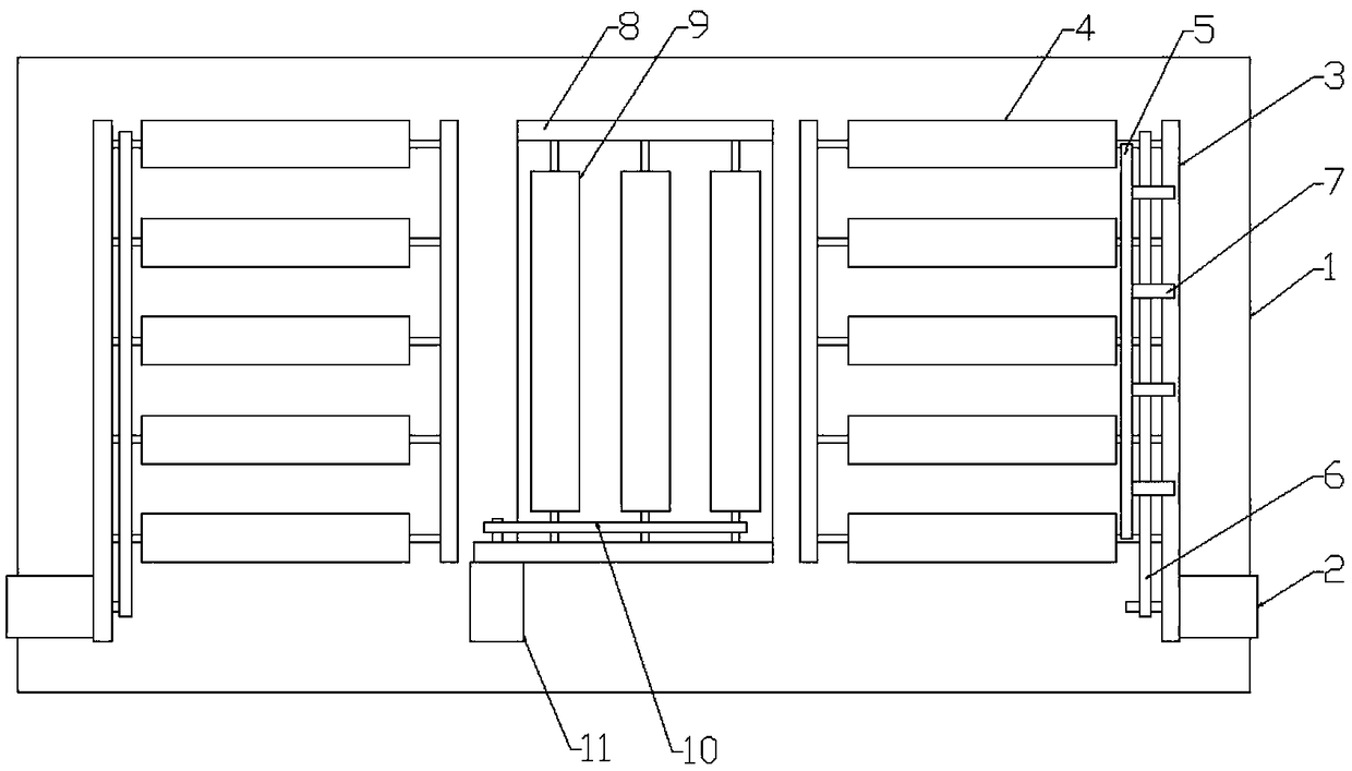
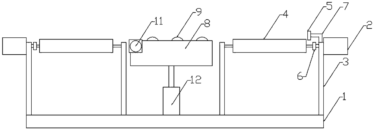
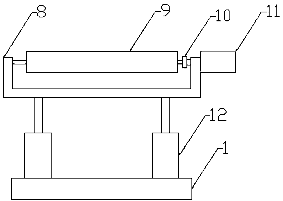
[0013] Figure 1-3 A specific embodiment of the present invention is shown: a feeding device for plate splicing welding, including a base 1, a bracket-3 is provided at both ends of the base 1, and a roller-4 is provided between the brackets-3, so that The side of described support one 3 is fixed with motor one 2, and described motor one 2 is connected with roller one 4 by transmission belt one 6, and described support one 3 side upper end is provided with L frame 7, and the front end of described L frame 7 is provided with Limiting plate 5, said limiting plate 5 is perpendicular to roller one 4, said base 1 middle part is provided with jacking device 12, said jacking device 12 upper end is provided with support two 8 that lifts up and down, said support two 8 is provided with roller 2 9, and the side of described bracket 2 8 is fixed with motor 2 11, and described motor 2 11 is connected with roller 2 9 through transmission belt 2 10, and described roller 2 9 and roller 1 4 mu...


PUM


Abstract

The invention discloses a feeding device for plate splicing welding. The feeding device comprises a base, wherein first supports are arranged at the two ends of the base; first rollers are arranged between the first supports, first motors are fixed on the side surfaces of the first supports, and the first motors are connected to the first rollers through first transmission belts; an L-shaped frameis arranged at the upper end of one side of one first support, a limiting plate is arranged at the front end of the L-shaped frame, the limiting plate is perpendicular to the first rollers, and a jacking device is arranged in the middle of the base; and a second support capable of ascending and descending vertically is arranged at the upper end of the jacking device, second rollers are arranged on the second support, a second motor is fixed on the side surface of the second support, the second motor is connected to the second rollers through a second transmission belt, and the second rollersare perpendicular to the first rollers. According to the feeding device for the plate spicing welding, the structure is simple, the manufacturing cost is low, the positions of two plates can be accurately adjusted and then the two plates are sent into a jointed plate welding machine, the manual adjusting time is saved, and the welding efficiency of the jointed plate welding is improved.

Description

technical field [0001] The invention relates to the field of water tank welding, in particular to a feeding device for plate splicing and welding. Background technique [0002] The raw material of the water tank is stainless steel plate, which is rolled and welded into the cylinder of the water tank, and the circular cover and the bottom of the water tank are cut on the plate, and welded to both ends of the cylinder to obtain a circular water tank. The plate in the factory The width of the roll is fixed. For the water tank whose height is greater than the width of the coil, it is necessary to splice multiple plates and then roll them into a cylinder. Set up transport rollers at both ends of the splicing machine, and separate the two spliced ​​plates from the two ends. The transport roller is pushed to the joint of the jigsaw machine, and the workers use the pry bar to adjust the position of the two plates so that the two ends of the two plates are aligned and kept parallel t...

Claims


Application Information

Patent Timeline
Patent Type & Authority Applications(China)
IPC IPC(8): B23K37/00B23K37/04
CPCB23K37/00B23K37/0443
Inventor 艾莉
Owner WUHU JUNRU THERMAL INSULATION MATERIAL CO LTD
Why Eureka
Try Eureka