
Creel for textile equipment

A technology of textile equipment and creel, applied in the field of textile equipment, can solve the problems of simple structure of textile creel, limited number of yarn bobbins, damage of textile creel, etc., and achieves the effects of easy use, simple structure and reasonable design

Inactive Publication Date: 2018-10-12
湖州吴兴永庆针纺织品有限公司
View PDF0 Cites 2 Cited by
  • Summary
  • Abstract
  • Description
  • Claims
  • Application Information

AI Technical Summary

Problems solved by technology

[0002] Textile machinery is a mechanical device that chemically processes natural fibers into various textiles that people need. With the progress of society, the textile industry has developed greatly. In the textile process, spinning needs to be wound on the bobbin, so , the textile creel is indispensable in the textile industry. The existing textile creel has a simple structure, and the height it can support is fixed, resulting in a limited number of bobbins that can be suspended. In addition, since the creel is located at the same The direction cannot be changed, so when there are many yarn bobbins hanging, it is easy to fall over, causing damage to the textile creel and unnecessary troubles. Therefore, the present invention proposes a creel for textile equipment to solve the above problems

Method used

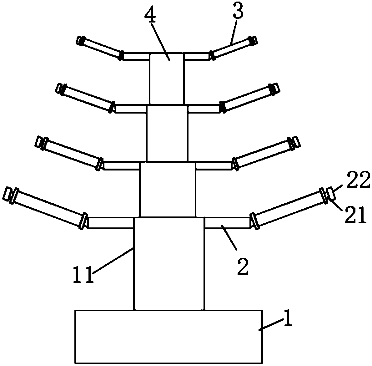
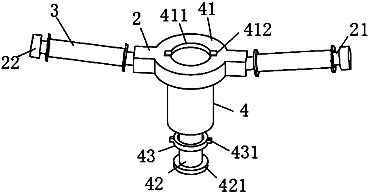

Image

  • Creel for textile equipment
  • Creel for textile equipment

Examples


Embodiment Construction

[0016] The following will clearly and completely describe the technical solutions in the embodiments of the present invention with reference to the accompanying drawings in the embodiments of the present invention. Obviously, the described embodiments are only some, not all, embodiments of the present invention. Based on the embodiments of the present invention, all other embodiments obtained by persons of ordinary skill in the art without making creative efforts belong to the protection scope of the present invention.

[0017] see Figure 1-2 , the present invention provides a technical solution: a creel for textile equipment, including a base 1 and a connecting frame 4, a base frame 11 is fixedly installed in the middle of the upper surface of the base base 1, and a fixed rod 2 is symmetrically installed on the upper end of the base frame 11 , the lower surface of the connecting frame 4 is fixedly installed with a connecting rod 42 vertically, and one end of the connecting r...


PUM


Abstract

The invention discloses a creel for textile equipment. The creel for the textile equipment comprises a base and connecting frames, wherein a bottom frame is fixedly mounted in the middle part of the upper surface of the base, and fixing rods are symmetrically mounted at the upper end of the bottom frame; connecting inserting rods are fixedly vertically mounted on the lower surfaces of the connecting frames; a threaded plate is fixedly mounted at one end, far away from the corresponding connecting frame, of each connecting inserting rod. According to the creel for the textile equipment, the threaded plates are fixedly mounted at the end parts of the connecting inserting rods; the connecting frames can be rotated to enable the threaded plates to be clamped to the upper part of the bottom frame through screw threads; in addition, a fixing sleeve ring movably sleeves the surface of each connecting inserting rod, and fixing clamping blocks are symmetrically arranged on the surfaces of the fixing sleeve rings, so that the position relation between each connecting frame and the bottom frame can be further fixed; the connection of adjacent connecting frames is similar to the connection between the bottom frame and the connecting frames; rotating shafts arranged on the adjacent connecting frames are vertical to each other by position, so that spools which are rotatably arranged on the rotating shafts can be dispersed and prevented from being accumulated in the same direction to cause tilting.

Description

technical field [0001] The invention relates to the technical field of textile equipment, in particular to a creel for textile equipment. Background technique [0002] Textile machinery is a mechanical device that chemically processes natural fibers into various textiles that people need. With the progress of society, the textile industry has developed greatly. In the textile process, spinning needs to be wound on the bobbin, so , the textile creel is indispensable in the textile industry. The existing textile creel has a simple structure and the height it can support is fixed, resulting in a limited number of bobbins that can be suspended. In addition, since the creel is located at the same The direction cannot be changed, so when there are many yarn bobbins hanging, it is easy to fall over, causing damage to the textile creel and unnecessary troubles. Therefore, the present invention proposes a creel for textile equipment to solve the above problems . Contents of the in...

Claims


Application Information

Patent Timeline
IPC IPC(8): B65H49/32
CPCB65H49/32B65H49/324B65H2701/31
Inventor 费建英
Owner 湖州吴兴永庆针纺织品有限公司
Learn More