
Structure for preventing telegraph pole upward pulling due to soil frost heaving

A technology of utility poles and frost heave, which is applied in the field of utility pole pulling, can solve the problems of large manpower and financial resources, high cost, and endangering the safety of the power grid, and achieve the effects of preventing water absorption, reducing swelling shear force, and reducing binding force

Active Publication Date: 2018-10-12
ELECTRIC POWER RES INST OF EAST INNER MONGOLIA ELECTRIC POWER +2
View PDF6 Cites 3 Cited by
  • Summary
  • Abstract
  • Description
  • Claims
  • Application Information

AI Technical Summary

Problems solved by technology

Although this method can alleviate or temporarily solve the phenomenon of pulling up electric poles in areas with severe frost heave to a certain extent, it cannot fundamentally or long-term solve this problem, and requires a lot of manpower and financial resources every year, and the implementation effect is limited
[0005] In summary, the existing technical solutions to the problem of pulling up electric poles still have problems such as low efficiency, high cost, and poor effect. Therefore, a new structure for preventing electric poles from being pulled up in areas with severe soil frost heaving is urgently needed. In order to better solve the problem of seriously endangering the safety of the power grid caused by the pulling of the utility pole

Method used


Image

  • Structure for preventing telegraph pole upward pulling due to soil frost heaving

Examples


Embodiment 1

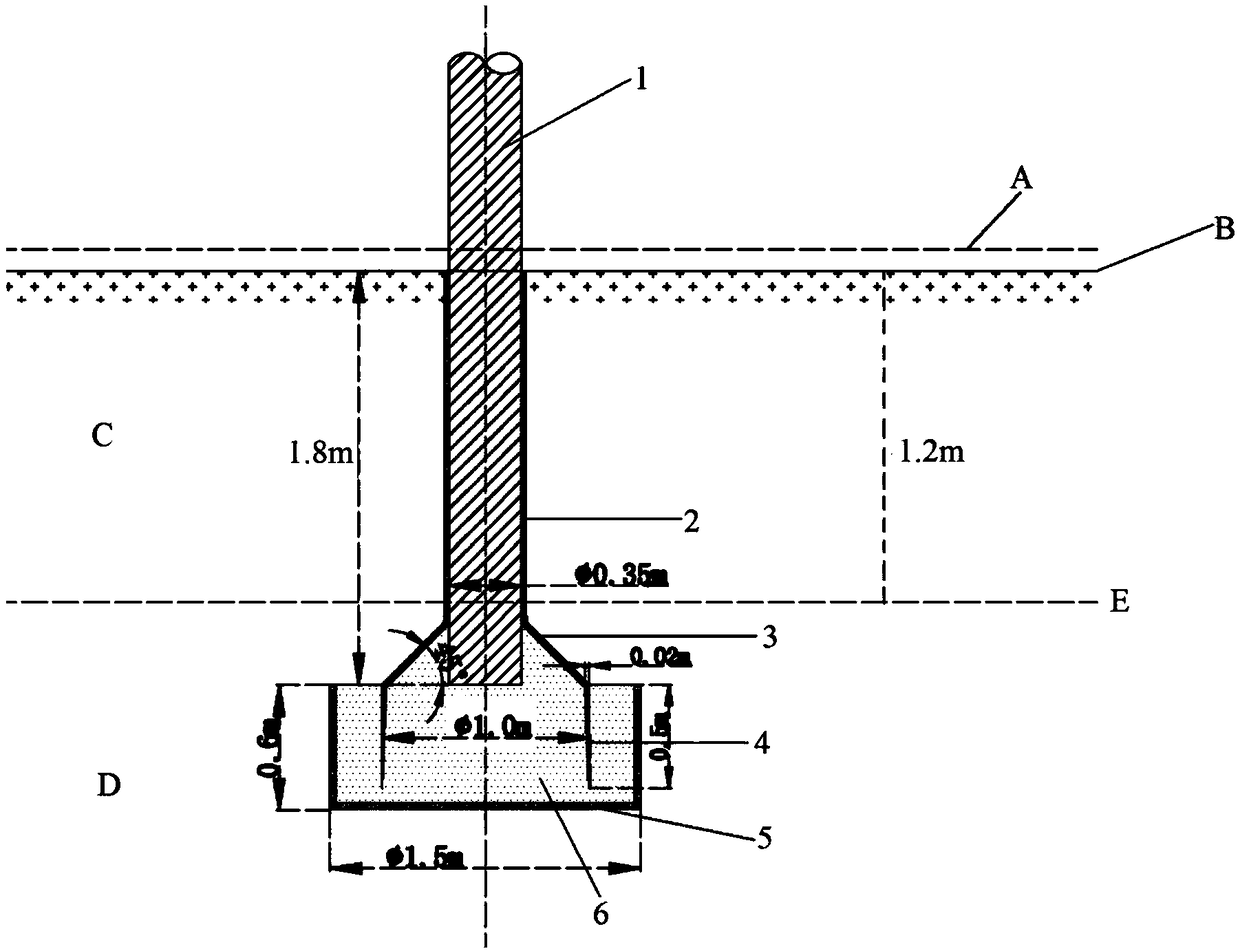
[0039] The burial depth of the utility pole 1 in the present embodiment is 1.8m, wherein the burial depth of the utility pole buried in the permafrost layer C is 0.6m, that is, buried in the permafrost layer above the boundary line E between the permafrost layer and the non-frozen layer The depth of the utility pole in C is 1.2m, the inner diameter of the cylinder 4 is 1.0m, the depth of the cylinder 4 is 0.5m, the thickness of the cylinder 4 is 0.02m, and the inner diameter of the circular waterproof layer 5 is 1.5m. The depth of waterproof layer 5 is 0.6m.

[0040] like figure 1 Shown, a kind of structure that prevents the utility pole from being pulled up caused by soil frost heaving, comprises: utility pole 1, drag-reducing layer 2, waterproof layer 5, sleeve, and described sleeve is made of stainless steel, is arranged on the utility pole 1 At the bottom end, the sleeve and the utility pole 1 are all arranged in the waterproof layer 5 .

[0041] The sleeve is composed o...

Embodiment 2

[0047] The burial depth of the utility pole 1 in the present embodiment is 2.0m, wherein the burial depth of the utility pole buried in the permafrost layer C is 0.4m, that is, buried in the permafrost layer above the boundary E of the permafrost layer and the non-frozen layer The depth of the utility pole in C is 1.6m, the inner diameter of the cylinder 4 is 1.0m, the depth of the cylinder 4 is 0.5m, the thickness of the cylinder 4 is 0.02m, and the inner diameter of the circular waterproof layer 5 is 1.5m. The depth of waterproof layer 5 is 0.6m.

[0048] A structure for preventing the uplifting of electric poles caused by soil frost heaving, comprising: electric pole 1, drag-reducing layer 2, waterproof layer 5, and sleeve, the sleeve is made of stainless steel and is arranged at the bottom of electric pole 1, Both the sleeve and the utility pole 1 are arranged in the waterproof layer 5 .

[0049] The sleeve is composed of a ring cover 3 and a cylindrical body 4 that is no...

Embodiment 3

[0055] The burial depth of the utility pole 1 in the present embodiment is 2.4m, wherein the burial depth of the utility pole buried in the permafrost layer C is 0.6m, that is, the permafrost layer buried in the permafrost layer and the frozen layer above the boundary line E of the non-frozen layer The depth of the utility pole in C is 1.8m, the inner diameter of the cylinder 4 is 1.0m, the depth of the cylinder 4 is 0.5m, the thickness of the cylinder 4 is 0.02m, and the inner diameter of the circular waterproof layer 5 is 1.5m. The depth of waterproof layer 5 is 0.6m.

[0056] A structure for preventing the uplifting of electric poles caused by soil frost heaving, comprising: electric pole 1, drag-reducing layer 2, waterproof layer 5, and sleeve, the sleeve is made of stainless steel and is arranged at the bottom of electric pole 1, Both the sleeve and the utility pole 1 are arranged in the waterproof layer 5 .

[0057] The sleeve is composed of a ring cover 3 and a cylindr...


PUM

PropertyMeasurementUnit
Buried depthaaaaaaaaaa
Depthaaaaaaaaaa
The inside diameter ofaaaaaaaaaa

Abstract

The invention relates to a structure for preventing telegraph pole upward pulling due to soil frost heaving. The structure for preventing telegraph pole upward pulling due to soil frost heaving comprises a telegraph pole, a sleeve, a waterproof layer and a drag reduction layer. The sleeve is arranged at the bottom end of the telegraph pole, and the sleeve and the telegraph pole are arranged in thewaterproof layer. The drag reduction layer is arranged on the surface of a pole foor of the telegraph pole, and the sleeve is constituted by a sleeve body and an annular cover which are fixedly connected. The upper end of the annular cover is in acute angle connection with the telegraph pole, and the upper end of the annular cover and the telegraph pole are fixedly connected. The edge of the lower portion of the sleeve body is in a blade shape, and the interior of the sleeve and the position between the sleeve and the waterproof layer are filled with dry and tamped fine sand. Through arrangement of acute angle connection between the upper end of the annular cover and the telegraph pole, acting force of soil frost heaving on telegraph pole upward pulling is converted into vertical downwardacting force, resistance of telegraph pole upward pulling is increased, and the problem of telegraph pole upward pulling due to soil frost heaving can be avoided well.

Description

technical field [0001] The invention belongs to the technical field of utility pole pulling up, and in particular relates to a structure for preventing electric utility pole pulling up in areas with severe soil frost heave. Background technique [0002] Taking the Genhe area as an example, because the area is located in the Daxing'anling forest area, there are many rainy weather, high latitude and little sunshine, and most of the transmission and distribution lines of the Genhe Power Supply Company were built in the 1960s, and the power grid system was controlled by the forestry system at that time. Built by itself, it is divided into three voltage levels: 110KV, 66KV and 10KV. In addition to the long-term structural design and construction of the line itself, most of the pole foundations of the utility poles are located in the swampy area of ​​the forest area, with high soil moisture content and serious soil frost heaving. [0003] Soil frost heaving and the existence of a...

Claims


Application Information

Patent Timeline
IPC IPC(8): E04H12/22
CPCE04H12/2246
Inventor 王永红钱文晓杨倩倩党乐祖向东郭金刚王博吴冠宇王鑫陶朱洪强
Owner ELECTRIC POWER RES INST OF EAST INNER MONGOLIA ELECTRIC POWER
Learn More