Direct-current fan failure monitoring system

A DC fan, fault monitoring technology, applied in the field of medical equipment, can solve the problems of inability to effectively detect the fan stall state, unable to take, fan burnout, etc.

Inactive Publication Date: 2018-10-12
CHONGQING JINSHAN MEDICAL INSTR CO LTD
View PDF8 Cites 4 Cited by
  • Summary
  • Abstract
  • Description
  • Claims
  • Application Information

AI Technical Summary

Problems solved by technology

[0003] However, the traditional fan failure detection can only detect the failure of the fan, but cannot take effective measures after the fan failure is detected
For example, when it is detected that the fan is in an overcurrent state, the fan cannot be quickly shut down or the power supply circuit of the fan is cut off, which will cause the fan to be burned out, further causing unnecessary economic losses. The fault detection is not comprehensive. Among them, when the fan is in a locked-rotor state, the blocked-rotor state of the fan cannot be effectively detected.

Method used


Image

  • Direct-current fan failure monitoring system
  • Direct-current fan failure monitoring system
  • Direct-current fan failure monitoring system

Examples


Embodiment Construction

[0043] The technical solutions in the embodiments of the present invention will be clearly and completely described below with reference to the accompanying drawings in the embodiments of the present invention. Obviously, the described embodiments are only a part of the embodiments of the present invention, but not all of the embodiments. Based on the embodiments of the present invention, all other embodiments obtained by those of ordinary skill in the art without creative efforts shall fall within the protection scope of the present invention.

[0044] The embodiment of the invention discloses a DC fan fault monitoring system, which quickly shuts down the DC fan in an overcurrent state, thereby avoiding economic losses.

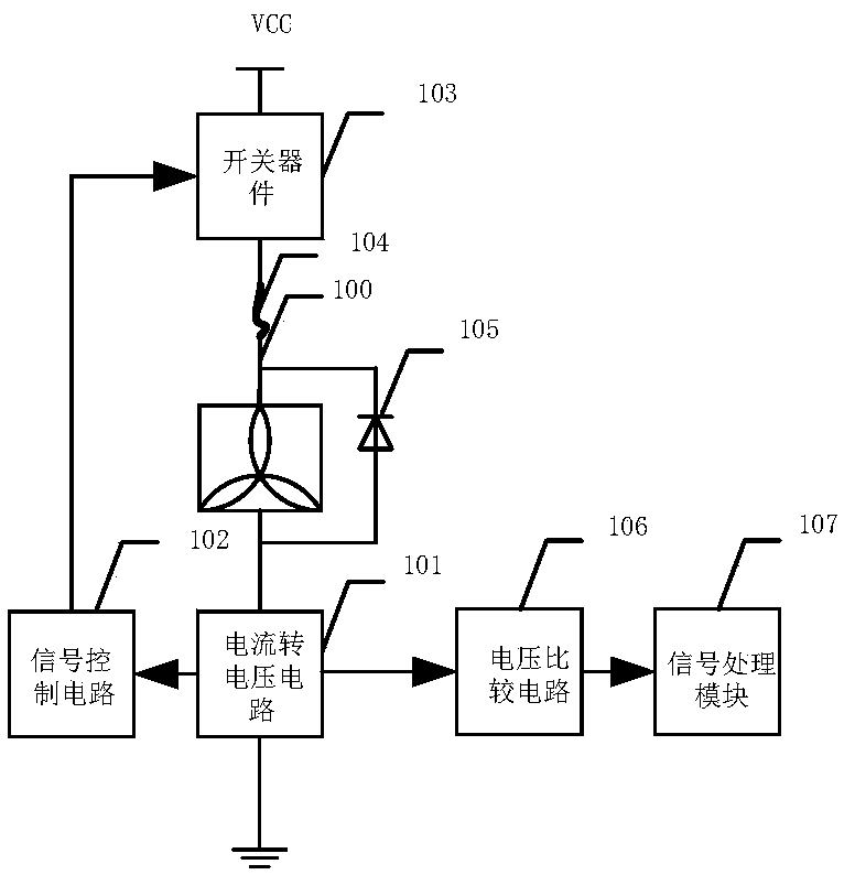
[0045] See figure 1 , figure 1 A schematic structural diagram of a fault monitoring system for a DC fan disclosed in an embodiment of the present invention, the system includes:

[0046] The current-to-voltage circuit 101 , the signal control circuit 102 ,...


PUM


Abstract

The invention discloses a direct-current fan failure monitoring system. When a voltage signal, detected by a signal control circuit and output by a current-to-voltage circuit, corresponding to a direct-current fan exceeds the direct-current fan set range, a control signal is output to control a switching element to be switched off, a power supply circuit of the direct-current fan is cut off, and therefore power cannot be supplied to the direct-current fan; when actual current, passing through the direct-current fan power supply circuit, of a protective pipe is larger than the maximum value ofa normal work current of the direct-current fan, fusing is carried out to cut off the direct-current fan power supply circuit; when the direct-current fan is closed, a diode provides a current discharge path, and the direct-current fan is protected against damage; the phenomenon that in the prior art, a control module processes signal delay, the fan is closed, the fan is burnt out, and unnecessaryeconomic losses are caused is avoided, through combination of a voltage comparison circuit and a signal processing module, the work state of the current direct-current fan can be displayed, a workercan conveniently take measures in time, and the direct-current fan is further prevented from being burnt out.

Description

technical field [0001] The invention relates to the field of medical equipment, in particular to a DC fan fault monitoring system. Background technique [0002] Because the electronic endoscope cold light source has many heating devices, it is necessary to use a fan to dissipate heat to prevent the internal components of the electronic endoscope from entering the protection mode due to overheating, and stop the light source and airflow supply of the electronic endoscope cold light source. Therefore, the normal operation of the fan has a decisive effect on the normal operation of the endoscope cold light source. Therefore, it is particularly important to detect the failure of the fan and deal with the fan after the failure. [0003] However, the traditional fan failure detection can only detect the failure of the fan, but cannot take effective measures after the fan failure is detected. For example, when it is detected that the fan is in an overcurrent state, the fan cannot...

Claims


Application Information

Patent Timeline
Patent Type & Authority Applications(China)
IPC IPC(8): F04D27/00
CPCF04D27/001F04D27/008
Inventor 蔡长春邓安鹏
Owner CHONGQING JINSHAN MEDICAL INSTR CO LTD
Why Eureka
Try Eureka