Unlock instant, AI-driven research and patent intelligence for your innovation.

Surrounding compression floating ground piezoelectric sensor for touchdown fuze

A piezoelectric sensor and ground piezoelectric technology, applied in the field of aerospace sensors, can solve problems such as unseen, low reliability, complex structure, etc., and achieve the effect of increasing lateral response capability, improving reliability, and reducing the interference of ground current.

Active Publication Date: 2018-10-12
BEIJING RES INST OF TELEMETRY +1
View PDF5 Cites 0 Cited by
  • Summary
  • Abstract
  • Description
  • Claims
  • Application Information

AI Technical Summary

Problems solved by technology

Due to the large change in the contact angle of the warhead, the piezoelectric sensor at this time is required to have a strong lateral response capability. The existing design of the piezoelectric sensor for the ground contact fuze generally uses three groups of piezoelectric sensitive elements to respond to X, Y, and Z respectively. Impact acceleration in three directions, and requires 3 output sockets, the X direction adopts compression design, Y and Z directions adopt shear design, the structure is relatively complex and the reliability is low
[0003] At present, there is no relevant report on the technology of surrounding compressed floating piezoelectric sensor for touchdown fuze

Method used


Image

  • Surrounding compression floating ground piezoelectric sensor for touchdown fuze
  • Surrounding compression floating ground piezoelectric sensor for touchdown fuze

Examples


Embodiment Construction

[0019] Below in conjunction with accompanying drawing and specific embodiment the present invention is described in further detail:

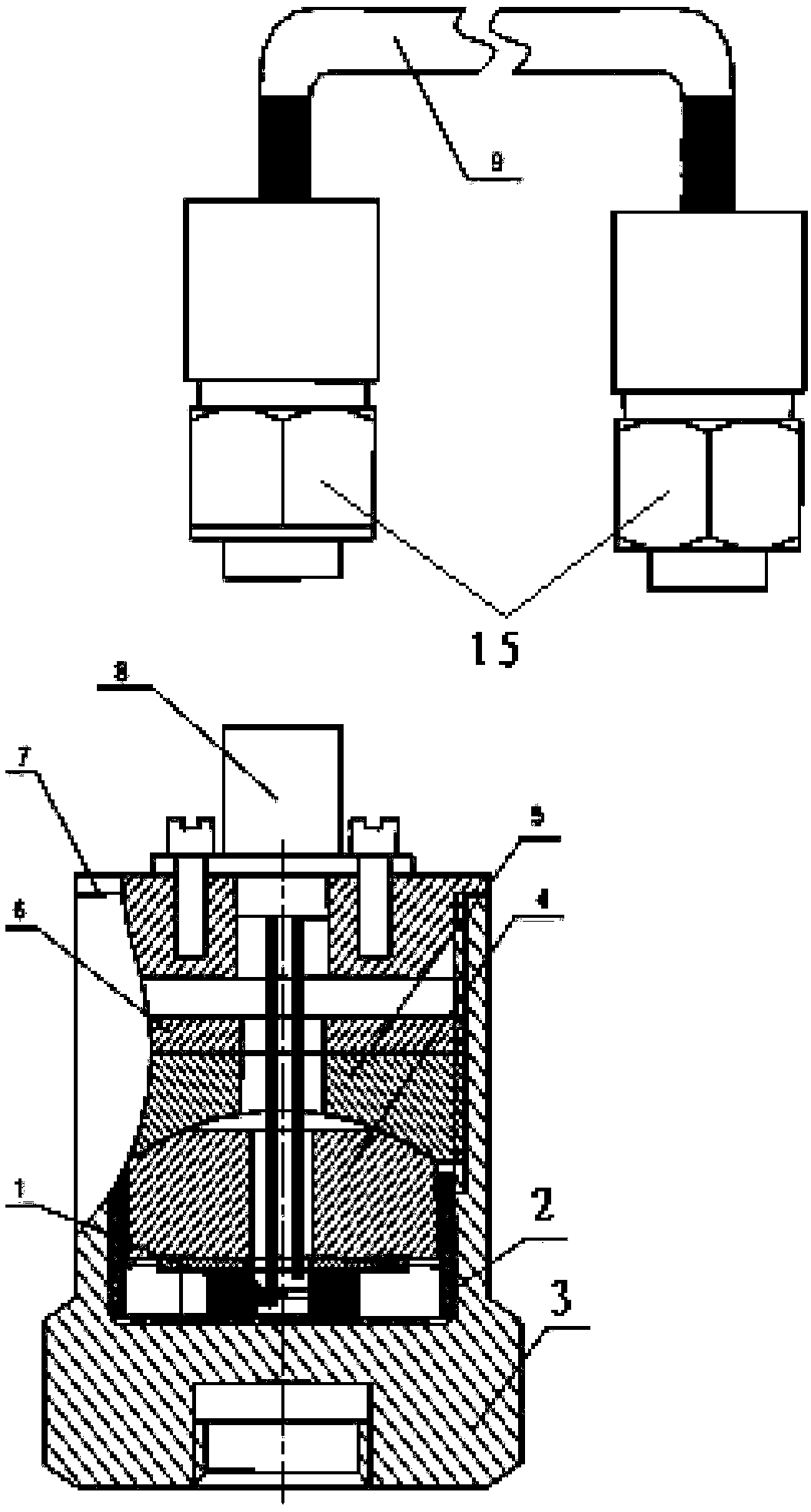
[0020] Such as figure 1 Shown is a schematic diagram of the structure of the floating piezoelectric sensor. It can be seen from the figure that the surrounding compressed floating piezoelectric sensor is used for the touchdown fuze, including the parallel sensitive body 1 of the floating piezoelectric stack, the shell 3, the anti-displacement ring 2, the mass block 4, Pre-tightening ring 5, anti-loosening ring 6, upper cover 7, two-core socket 8 and output low-noise cable 9; wherein, the housing 3 is a hollow cylindrical structure with an upper opening; the anti-displacement ring 2 is a cylindrical structure with an upper opening; The opening of the anti-displacement ring 2 is vertically attached to the inner bottom of the shell 3; the anti-displacement ring 2 is made of F4 material; and the inner wall of the anti-displacement ring 2 is a steppe...


PUM


Abstract

The invention provides a surrounding compression floating ground piezoelectric sensor for a touchdown fuze, and relates to the technical field of aerospace sensors. The surrounding compression floating ground piezoelectric sensor for the touchdown fuze comprises floating ground piezoelectric stack parallel sensitive materials, a shell, an anti-dislocation ring, a mass block, a pre-tightening ring,an anti-loosening ring, an upper cover, a two-core socket and output low noise cables. The anti-dislocation ring is vertically adhered on the bottom surface in the shell with the opening upward. Thefloating ground piezoelectric stack parallel sensitive materials are fixedly installed at the center of the bottom surface of the anti-dislocation ring. The mass block is fixedly installed on the toppart of the floating ground piezoelectric stack parallel sensitive materials. The pre-tightening ring is fixedly installed on the top part of the mass block. The anti-loosening ring is fixedly installed on the top part of the pre-tightening ring. The upper opening of the shell is sealed by the upper cover. The two-core socket is fixedly installed on the top part of the upper cover. One end of eachoutput low noise cables is connected with the two-core socket, and the other end of each output low noise cables is connected with an external electronic switch. One point grounding of the system canbe ensured by the internal floating ground design and the interference of the ground current can be reduced, and one point grounding of the system is realized and the reliability of the product can be enhanced.

Description

technical field [0001] The invention relates to the technical field of aerospace sensors, in particular to a peripheral compression floating piezoelectric sensor for grounding fuzes. Background technique [0002] The characteristic of the touchdown fuze is that it detonates immediately after the fuze touches the target. Piezoelectric touchdown fuzes are widely used in anti-tank bombs, aerial bombs and missiles because of their high instantaneousness. Due to the large change in the contact angle of the warhead, the piezoelectric sensor at this time is required to have a strong lateral response capability. The existing design of the piezoelectric sensor for the ground contact fuze generally uses three groups of piezoelectric sensitive elements to respond to X, Y, and Z respectively. The shock acceleration in three directions requires three output sockets. The X direction adopts compression design, and the Y and Z directions adopt shear design. The structure is relatively comp...

Claims


Application Information

Patent Timeline
IPC IPC(8): G01L1/16G01L5/00
CPCG01L1/16G01L5/0052
Inventor 鲁敏何勤彭泳卿
Owner BEIJING RES INST OF TELEMETRY
Features
  • R&D
  • Intellectual Property
  • Life Sciences
  • Materials
  • Tech Scout
  • Unparalleled Data Quality
  • Higher Quality Content
  • 60% Fewer Hallucinations
Learn More