
Three-axis self-calibration method for vehicle-mounted acceleration sensor

An acceleration sensor and acceleration sensor technology, applied in the testing/calibration of speed/acceleration/shock measurement equipment, speed/acceleration/shock measurement, instruments, etc., can solve the problem of not being able to provide real-time three-axis, and shorten the calibration time , quick results

Inactive Publication Date: 2018-10-12
QUECLINK WIRELESS SOLUTIONS HF CO LTD
View PDF6 Cites 2 Cited by
  • Summary
  • Abstract
  • Description
  • Claims
  • Application Information

AI Technical Summary

Problems solved by technology

[0003] The technical problem to be solved by the present invention is to solve the problem that the acceleration sensor in the prior art cannot provide real-time three-axis force changes

Method used


Image

  • Three-axis self-calibration method for vehicle-mounted acceleration sensor
  • Three-axis self-calibration method for vehicle-mounted acceleration sensor
  • Three-axis self-calibration method for vehicle-mounted acceleration sensor

Examples


no. 1 example

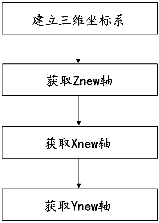
[0036] refer to figure 1 , the present embodiment provides a three-axis self-calibration method for a vehicle-mounted acceleration sensor, including establishing a three-dimensional coordinate system, obtaining Z new Axis, Get X new Axis and get Y new axis.

[0037] Among them, establishing a three-dimensional coordinate system includes:

[0038] Establish the three-dimensional coordinate system O-XYZ based on the acceleration sensor and the three-dimensional coordinate system O-X based on the driving direction of the car new Y new Z new , let the three-dimensional coordinate system O-XYZ and the three-dimensional coordinate system 0-X new Y new Z new The transformation equations for are:

[0039] x new =a1*X+b1*Y+c1*Z;

[0040] Y new =a2*X+b2*Y+c2*Z;

[0041] Z new =a3*X+b3*Y+c3*Z.

[0042] Among them, get Z new Axes include:

[0043] At the moment of vehicle ignition, the acceleration sensor is only affected by gravity G, and the opposite direction of gravit...

no. 2 example

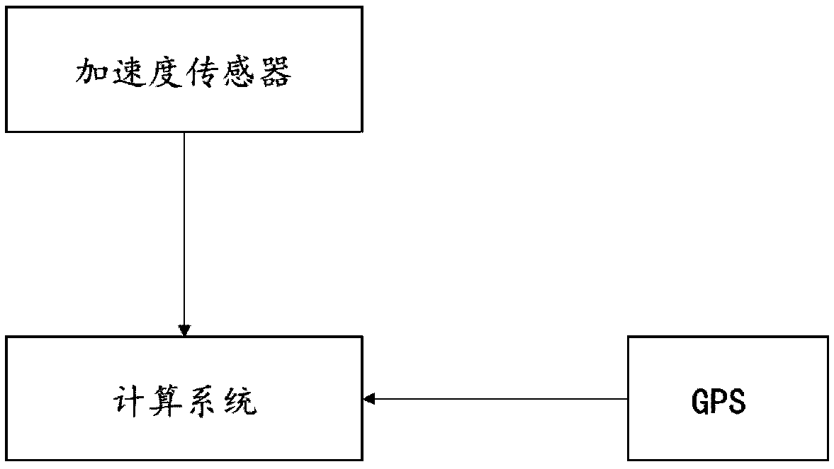
[0065] refer to figure 2 , this embodiment provides a three-axis self-calibration system for a vehicle-mounted acceleration sensor, including an acceleration sensor, a GPS, and a computing system.

[0066] The three-dimensional coordinate system based on the acceleration sensor is O-XYZ, and the three-dimensional coordinate system based on the driving direction of the car is O-X new Y new Z new , let the three-dimensional coordinate system O-XYZ and the three-dimensional coordinate system O-X new Y new Z new The transformation equations for are:

[0067] x new =a1*X+b1*Y+c1*Z;

[0068] Y new =a2*X+b2*Y+c2*Z;

[0069] Z new =a3*X+b3*Y+c3*Z.

[0070] Among them, GPS is used to collect vehicle speed to determine whether the vehicle is in an accelerated state.

[0071] When the GPS senses that the vehicle is accelerating, it triggers the computing system to calculate X new axis:

[0072] The on-board acceleration sensor is subjected to a resultant force towards X n...

no. 3 example

[0087] The present invention also provides a method for monitoring driving habits. First, the method described in the first embodiment is used to calibrate the vehicle-mounted acceleration sensor.

[0088] Then within the preset time interval Δt, calculate the force variation Δx of the vehicle in the forward direction. If Δx is greater than the preset threshold, it will be recorded as a bad driving habit; otherwise, it will be a normal driving habit.

[0089] The technical solution can accurately collect driving habits.


PUM


Abstract

The invention discloses a three-axis self-calibration method for a vehicle-mounted acceleration sensor. The method comprises the steps that a three-dimensional coordinate system O-XYZ based on an acceleration sensor and a three-dimensional coordinate system O-XnewYnewZnew based on a vehicle driving direction are established; a Znew axis is acquired, at a moment of vehicle ignition, the acceleration sensor is only affected by the gravity G, the opposite direction of the gravity G is the Znew axis in O-XnewYnewZnew; an Xnew axis is acquired, when the vehicle is accelerated, the acceleration sensor is subjected to the action of a resultant facing an Xnew direction, and Xnew axis is calculated through the resultant; a Ynew axis is acquired, the Ynew axis is calculated through the right-hand screw rule. The three-axis self-calibration method for the vehicle-mounted acceleration sensor can calibrate the three-axis direction of the vehicle-mounted acceleration sensor, can provide real-time three-axis stress conditions, can more accurately reflect driving habits of a driver, and can more accurately restore a real situation of vehicle collision.

Description

technical field [0001] The invention relates to the field of acceleration sensor calibration, in particular to a three-axis self-calibration method for a vehicle-mounted acceleration sensor. Background technique [0002] Vehicle electronic products need to accurately provide the real-time three-axis force of the vehicle as the basis for driving habit training and vehicle collision recovery. At present, the acceleration sensors on the market can only provide the magnitude of the three-axis force with a fixed sensor direction. At the same time, there are many uncertain factors in the position and horizontal angle of the vehicle-mounted electronic products, which eventually lead to the acceleration sensor being unable to provide real-time three-axis (forward Direction, lateral direction, vertical direction) force changes. Contents of the invention [0003] The technical problem to be solved by the present invention is to solve the problem that the acceleration sensor in the ...

Claims


Application Information

Patent Timeline
Patent Type & Authority Applications(China)
IPC IPC(8): G01P21/00
CPCG01P21/00
Inventor 袁学涛
Owner QUECLINK WIRELESS SOLUTIONS HF CO LTD
Learn More