

Fishing pendant
A fishing pendant and integrated technology, applied in the field of fishing pendants, can solve the problems of rebound injury, fish pendant and hook fishing line falling off, fish pendant easy to fall into rock cracks, etc., and achieve the effect of safe use
- Summary
- Abstract
- Description
- Claims
- Application Information
AI Technical Summary
Problems solved by technology
Method used
Image

Examples
Embodiment Construction
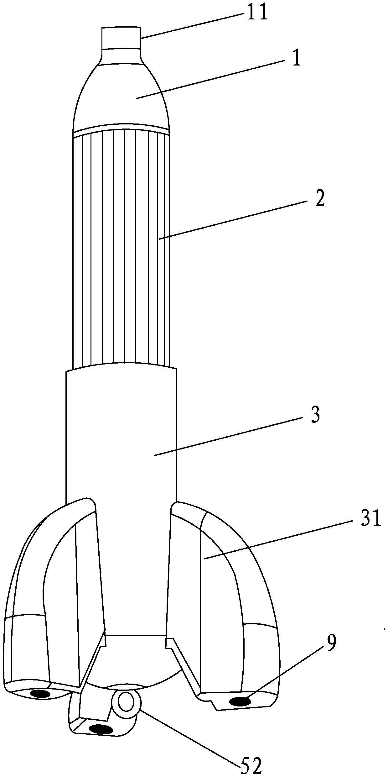
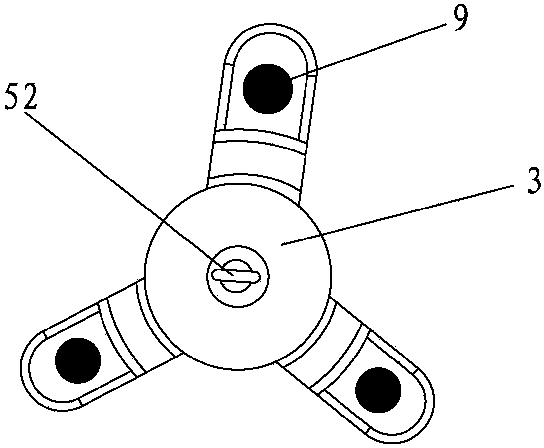
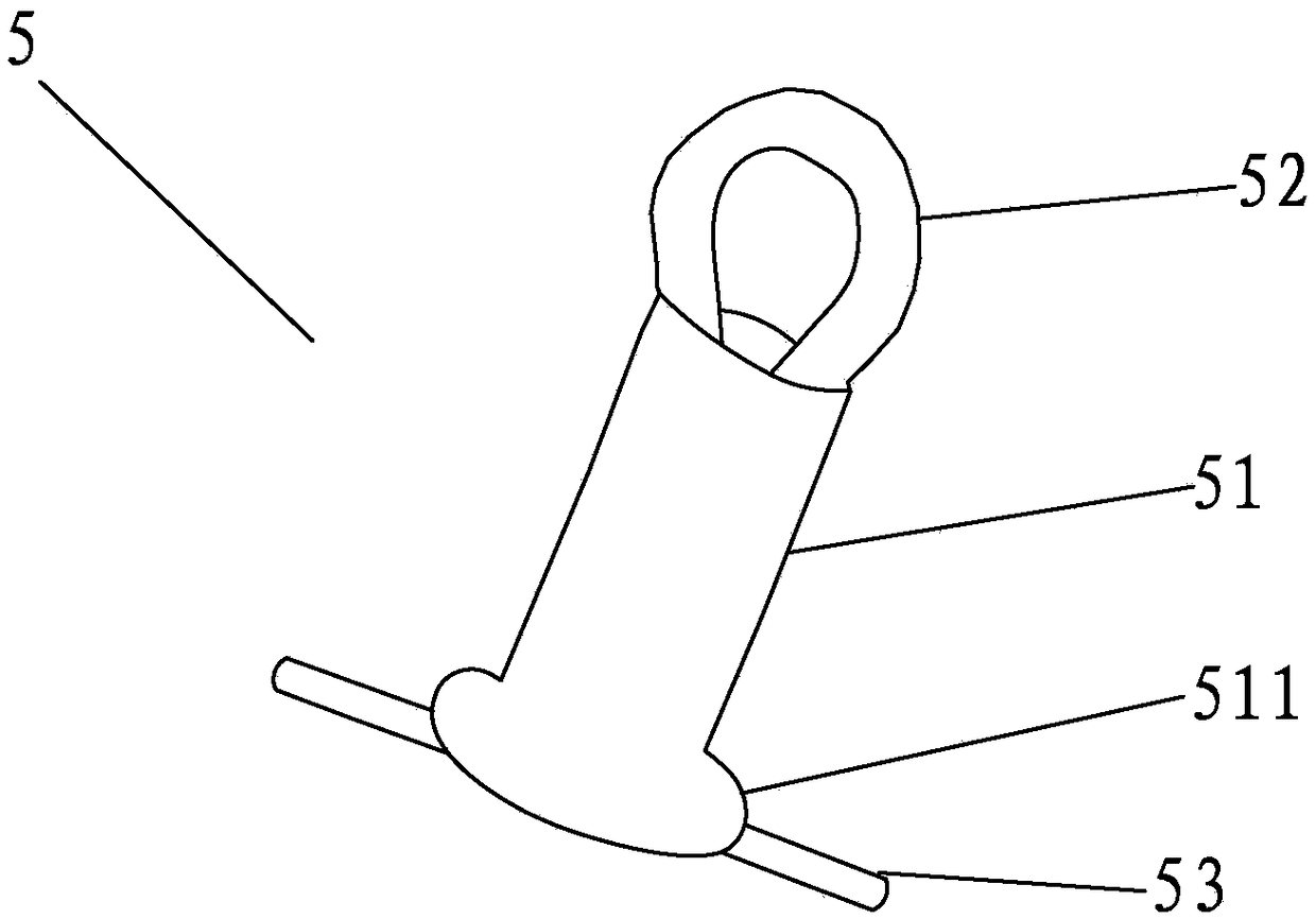
[0025] A kind of fishing weight of the present invention, such as Figure 1-4 As shown, it includes a weight head 1, an aluminum connector 2 and a plastic head 3. The aluminum connector 2 is a hollow aluminum tube with open ends, that is, the aluminum connector 2 is a hollow cylinder structure, and the weight head 1 is a lead block. body, the lead block body is provided with a reinforcing rod 4 integrally cast with the lead block body, one end of the counterweight head 1 extends into the first end port of the aluminum connector 2 and is fixed together with the aluminum connector 2, and the counterweight head 1 The other end is outside the aluminum connector 2, and the plastic head 3 is a hollow pipe body whose one end is an open end and the other end is a closed end. And be fixedly connected with the plastic head 3, the plastic head 3 is fixedly installed with the threading coil 5 outside the closed end of the plastic head 3, and the outer wall of the plastic head 3 is protrud...
PUM
 Abstract
Description
Claims
Application Information