
Surgical Robotic System

A robotic system and surgical technology, applied in surgical robots, surgical navigation systems, surgical manipulators, etc., to solve problems such as inability to move objects

Active Publication Date: 2022-03-22
GLOBUS MEDICAL INC
View PDF7 Cites 6 Cited by
  • Summary
  • Abstract
  • Description
  • Claims
  • Application Information

AI Technical Summary

Problems solved by technology

[0007] One problem is that tracking sensors are usually rigidly attached to part of the object to be tracked and usually cannot move on the object itself

Method used


Image

  • Surgical Robotic System
  • Surgical Robotic System
  • Surgical Robotic System

Examples


Embodiment Construction

[0039] It should be understood that the invention is not limited in its application to the details of construction and arrangement of components set forth in this description or shown in the drawings. The teachings of the invention can be used and practiced in other embodiments and of being practiced or carried out in various ways. Also, it is to be understood that the phraseology and terminology used herein are for the purpose of description and should not be regarded as limiting. The use of "comprising", "comprising" or "having" and variations thereof herein is meant to encompass the items listed thereafter and their equivalents as well as additional items. Unless specified or limited otherwise, the terms "mount," "connect," "support," and "coupling" and variations thereof are used broadly and include direct and indirect mounting, connections, supports, and couplings. Furthermore, "connected" and "coupled" are not limited to physical or mechanical connections or couplings. ...


PUM


Abstract

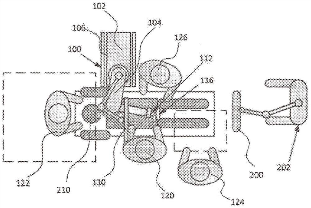
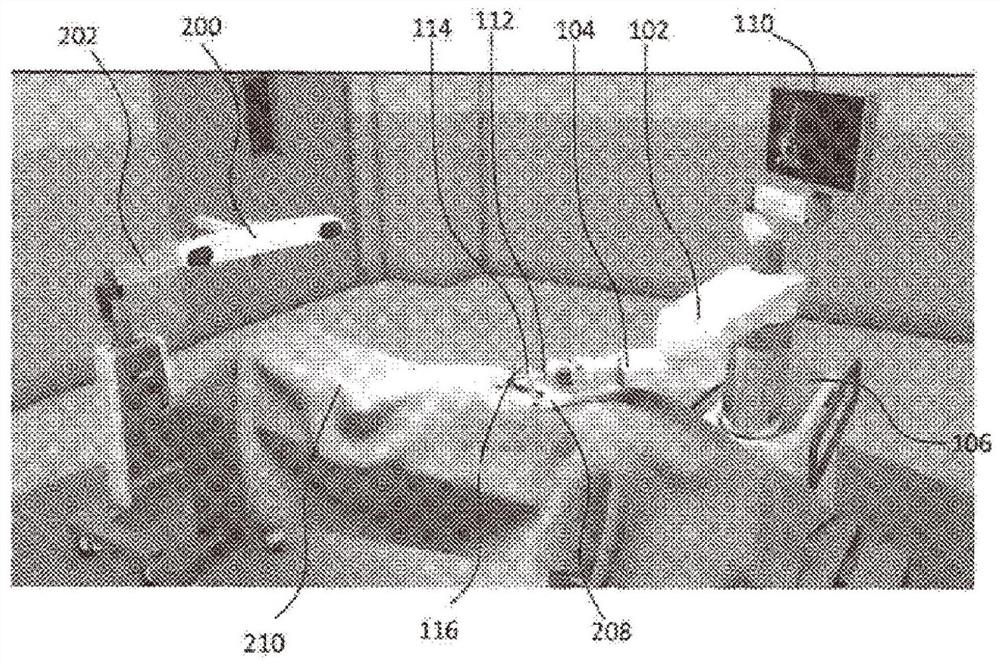
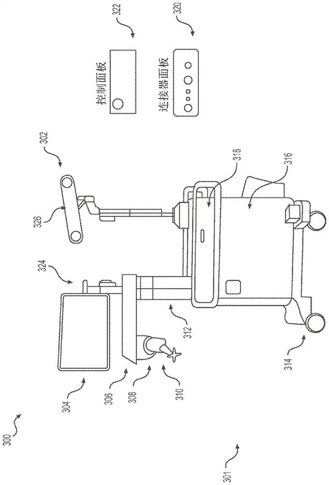
The present invention relates to a surgical robotic system that may include a robot having a robotic base, a robotic arm coupled to the robotic base, and an end effector coupled to the robotic arm. The end effectors, surgical instruments, patients and / or other objects to be tracked include active and / or passive tracking markers. A camera, such as a stereo photogrammetric infrared camera, can detect the tracking markers, and the robot determines the three-dimensional position of the object from the tracking markers.

Description

[0001] Cross References to Related Applications [0002] This application is a continuation-in-part of U.S. Patent Application No. 15 / 157,444, filed May 18, 2016, which is a continuation-in-part of U.S. Patent Application No. 15 / 095,883, filed April 11, 2016, which is a continuation-in-part of U.S. Patent Application No. 14 / 062,707, filed October 24, 2013, which is a continuation-in-part of U.S. Patent Application No. 13 / 924,505, filed June 21, 2013, which claims 2012 Priority to Provisional Application No. 61 / 662,702, filed June 21, 2013, and claiming priority to Provisional Application No. 61 / 800,527, filed March 15, 2013, the entire contents of which are incorporated by reference in their entirety for all purposes Incorporated into this article. technical field [0003] The present invention relates to position recognition systems, and in particular to end effector and tool tracking and manipulation during robotic assisted surgery. Background technique [0004] Positio...

Claims


Application Information

Patent Timeline
Patent Type & Authority Patents(China)
IPC IPC(8): A61B34/30A61B34/20
CPCA61B34/20A61B34/30A61B34/70A61B34/77A61B2034/2046A61B2034/2051A61B2034/2055A61B2034/305A61B17/1757A61B17/34A61B17/7089A61B2017/00477A61B90/11A61B2090/3983A61B2090/0811A61B2034/107A61B2090/3937A61B2090/3945A61B2090/3991A61B2090/376A61B2090/3764A61B90/96A61B90/98A61B5/064A61B17/1642A61B17/1671A61B2017/00876A61B2505/05A61B2034/2057A61B2034/2072A61B34/32A61B2090/034A61B17/7083A61B17/7001A61B17/17A61B50/13A61B90/37
Inventor N·R·克劳福德N·约翰逊B·马索夫K·张
Owner GLOBUS MEDICAL INC
Learn More