Numerically-controlled machine tool housing

A technology for CNC machine tools and housings, which is applied to metal processing machinery parts, maintenance and safety accessories, metal processing equipment, etc., and can solve the problems of occupying the surrounding space of CNC machine tools, failing to provide a structure for cleaning waste, and inconvenient placement of facilities. , to achieve the effect of increasing the range of use

Inactive Publication Date: 2018-10-16
芜湖遥帆电子科技有限公司
View PDF1 Cites 2 Cited by
  • Summary
  • Abstract
  • Description
  • Claims
  • Application Information

AI Technical Summary

Problems solved by technology

However, this patent document fails to provide a structure for cleaning waste, and when the sliding door is opened, it will take up extra space around the CNC machine tool, causing inconvenience to the placement of nearby facilities

Method used


Image

  • Numerically-controlled machine tool housing
  • Numerically-controlled machine tool housing
  • Numerically-controlled machine tool housing

Examples


Embodiment 1

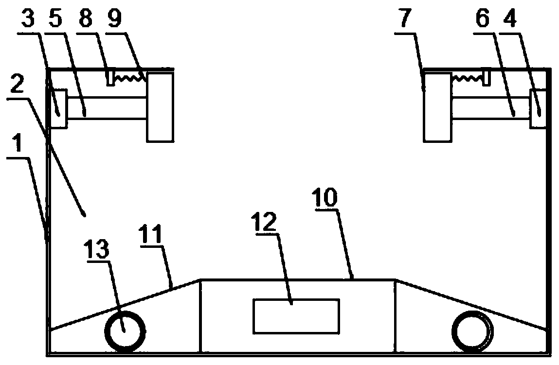
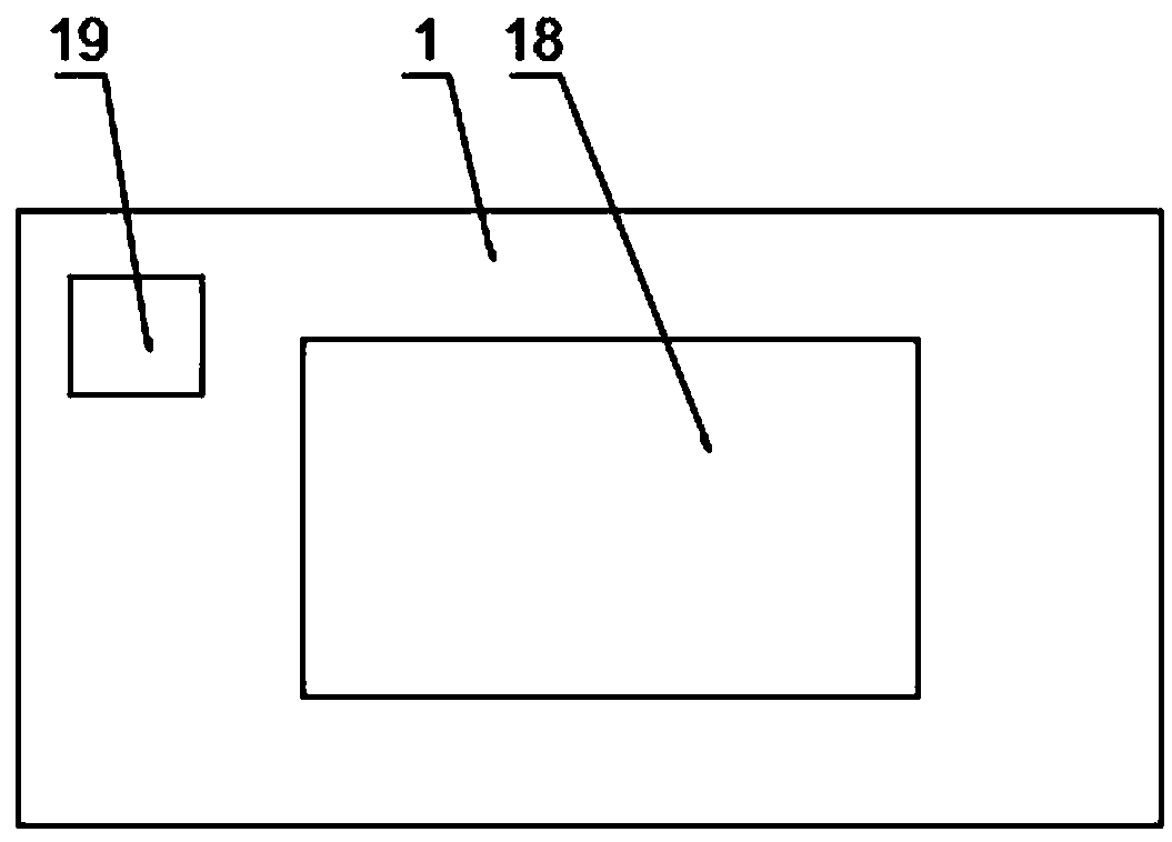
[0019] Such as Figure 1-3 As shown, the present invention provides a CNC machine tool cover, including a cover body 1, a cavity 2, a first base 3, a second base 4, a first telescopic rod 5, a second telescopic rod 6, a clamp 7, and a connecting rod 8. Protective cover 9, workbench 10, inclined plate 11, battery 12, solenoid 13, opening door 14, hinge 15, handle 16, waste collection door 17, observation window 18 and controller 19, cover body 1 The inside is provided with a cavity 2, and the inner side walls of the cavity 2 are respectively provided with a first base 3 and a second base 4, and one end of the first base 3 is provided with a first telescopic rod 5, and the second base 3 One end of the first telescopic rod 6 is provided with a second telescopic rod 6, one end of the first telescopic rod 5 and the second telescopic rod 6 are provided with a clamp 7, the bottom end of the cavity 2 is provided with a workbench 10, and both sides of the workbench 10 are provided with...


PUM


Abstract

The invention discloses a numerically-controlled machine tool housing. The numerically-controlled machine tool housing comprises a housing body. An accommodating cavity is formed in the housing body.A first base and a second base are arranged on the two side walls inside the accommodating cavity correspondingly. A first telescopic rod is arranged at one end of the first base. A second telescopicrod is arranged at one end of the second base. Clamps are arranged at one ends of the first telescopic rod and the second telescopic rod correspondingly. A workbench is arranged at the bottom end of the accommodating cavity. Oblique plates are arranged on the two sides of the workbench correspondingly. Solenoids are arranged inside the oblique plates correspondingly. A battery is arranged inside the workbench. According to the numerically-controlled machine tool housing, by arranging the clamps at the top end of the accommodating cavity, the housing body is made to be applicable to widths of executing elements of different numerically-controlled machine tools, and accordingly, the application range of the housing body is greatly expanded; and by arranging the solenoids inside the oblique plates correspondingly, wastes produced during machining can be firmly adsorbed to the surfaces of the oblique plates under the effect of a magnetic field, and when needing to be cleared, the wastes can be collected in a unified mode by interrupting power supply to the solenoids.

Description

technical field [0001] The invention relates to a machine tool cover, in particular to a numerical control machine tool cover, which belongs to the field of numerical control machine tools. Background technique [0002] Patent document CN205968442U discloses a protective outer cover for numerically controlled machine tools, including a cover body, a left sliding door and a right sliding door. Both sides of the cover body are provided with cooling ports, and legs are provided under the cover body. The surface of the body is provided with a left sliding door and a right sliding door, the surfaces of the left sliding door and the right sliding door are provided with handle grooves, the surface of the left sliding door is provided with an observation window and a temperature display screen, and the left sliding door There is a slide rail under the right sliding door, a fresh water tank and a waste water tank are arranged under the sliding rail, a wiper is provided on the inner s...

Claims


Application Information

Patent Timeline
Patent Type & Authority Applications(China)
IPC IPC(8): B23Q11/08B23Q11/00
CPCB23Q11/0891B23Q11/0064
Inventor 邓海
Owner 芜湖遥帆电子科技有限公司
Why Eureka
Try Eureka