
Foaming mold of PU headrest mold core connecting rod turnover mechanism

A technology of flipping structures and foaming molds, which is applied in the field of foaming molds. It can solve the problems of occupying a large space of the mold, difficulty in taking products, and shortage of cylinder strokes, and achieve uniform force, avoid insufficient driving strokes, and reasonable layout. Effect

Inactive Publication Date: 2018-10-16
NANTONG CHAODA EQUIP CO LTD
View PDF5 Cites 2 Cited by
  • Summary
  • Abstract
  • Description
  • Claims
  • Application Information

AI Technical Summary

Problems solved by technology

[0002] The automotive PU headrest foaming mold usually includes an upper mold, a lower mold and a mold core. The mold core is connected to the upper mold. When the mold is opened, the product goes to the upper mold together with the mold core. The cylinder pushes the mold core and the product, and then the operator removes the product. This structure has the disadvantages of difficulty in taking the product and occupying a large space inside the mold. There are problems such as stroke shortage and asynchronous turning, so we need to design a foaming mold that ensures that the connecting rod pushes the mold core to turn over synchronously, so as to solve the above technical problems

Method used


Image

  • Foaming mold of PU headrest mold core connecting rod turnover mechanism
  • Foaming mold of PU headrest mold core connecting rod turnover mechanism
  • Foaming mold of PU headrest mold core connecting rod turnover mechanism

Examples


Embodiment Construction

[0016] The following will clearly and completely describe the technical solutions in the embodiments of the present invention with reference to the accompanying drawings in the embodiments of the present invention. Obviously, the described embodiments are only some, not all, embodiments of the present invention. Based on the embodiments of the present invention, all other embodiments obtained by persons of ordinary skill in the art without creative efforts fall within the protection scope of the present invention.

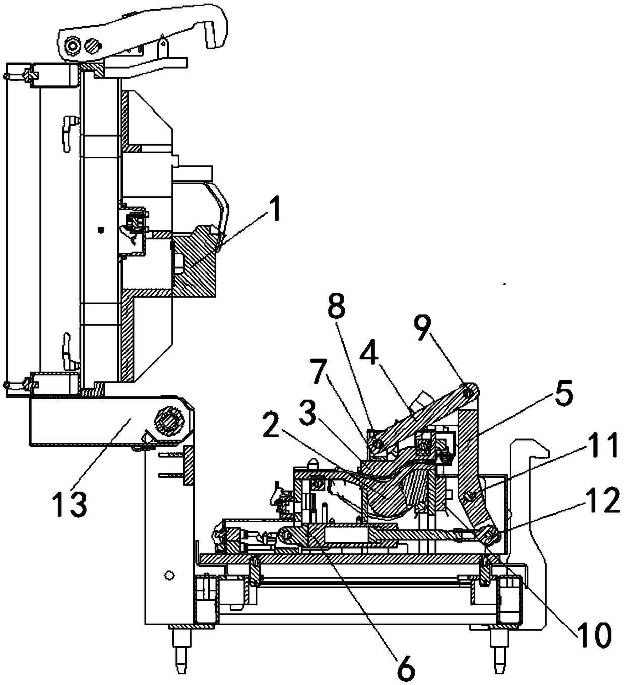
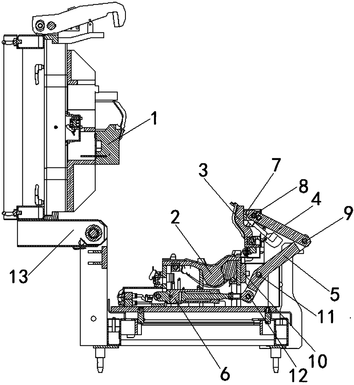
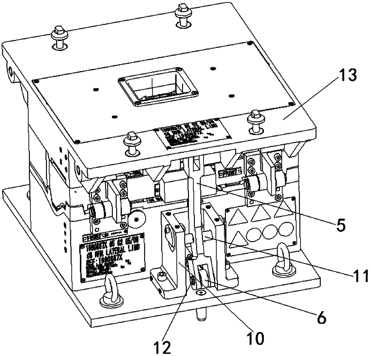
[0017] In a specific embodiment of the present invention, as Figure 1 to Figure 3 As shown, a foaming mold with a PU headrest mold core connecting rod overturn structure is specifically disclosed, including an upper mold 1, a lower mold 2, a mold core 3 and a connecting rod overturning mechanism, and the upper mold 1 and the lower mold 2 are connected , the upper mold 1 and the lower mold 2 are fixed on the mold base 13, and the mold base 13 adopts a hinged openin...


PUM


Abstract

The invention relates to the technical field of foaming molds, and particularly discloses a foaming mold of a PU headrest mold core connecting rod turnover mechanism. The foaming mold comprises an upper mold, a lower mold, a mold core and the connecting rod turnover mechanism. The upper mold is connected with the lower mold. The mold core is arranged between the upper mold and the lower mold. Theconnecting rod turnover mechanism is arranged in the middle of the mold core and comprises a straight connecting rod, a bent connecting rod and a flat air cylinder. One end of the straight connectingrod is fixed to the center of the mold core through a first fixing seat, and the other end of the straight connecting rod is connected with the bent connecting rod. The bent connecting rod is connected with the flat air cylinder, and the flat air cylinder is fixed to the lower mold. The foaming mold is compact in structure, reasonable in layout and convenient to operate; operators can take products and clean the mold core conveniently; the connecting rod turnover mechanism is arranged in the center of the mold core, the mold core is stressed evenly and turned over synchronously; the problem that the drive stroke of the air cylinder is insufficient is avoided; and the air cylinder is arranged at the bottom of the lower mold, use space is reduced, and the problem that space in the mold is insufficient is effectively avoided.

Description

technical field [0001] The invention relates to the technical field of foaming molds, in particular to a foaming mold with a PU headrest mold core connecting rod reversing structure. Background technique [0002] The automotive PU headrest foaming mold usually includes an upper mold, a lower mold and a mold core. The mold core is connected to the upper mold. When the mold is opened, the product goes to the upper mold together with the mold core. The cylinder pushes the mold core and the product, and then the operator removes the product. This structure has the disadvantages of difficulty in taking the product and occupying a large space inside the mold. There are problems such as stroke shortage and asynchronous turning, so we need to design a foaming mold that can ensure that the connecting rod pushes the mold core to turn over synchronously, so as to solve the above technical problems. Contents of the invention [0003] The purpose of this invention is to provide a foam...

Claims


Application Information

Patent Timeline
Patent Type & Authority Applications(China)
IPC IPC(8): B29C44/58
CPCB29C44/58
Inventor 冯建军陈亮顾林峰彭杰
Owner NANTONG CHAODA EQUIP CO LTD
Learn More