
Internet router reticle interface machining equipment

A technology for processing equipment and routers, which is applied in the direction of manufacturing tools, punching machines, presses, etc., and can solve the problem that there is no way to process square metal sheets.

Active Publication Date: 2018-10-16
日照法桐信息技术有限公司
View PDF7 Cites 7 Cited by
  • Summary
  • Abstract
  • Description
  • Claims
  • Application Information

AI Technical Summary

Problems solved by technology

The present invention is equipped with a slide rail and a slide block, and the staff can pull the first mold and the second mold out of the slide rail through the slide block, which is convenient for the staff to operate and use. Block, detachable installation between the first mold and the second mold, but the disadvantage of this invention is that there is no way to process the square metal sheet in the USB type router network cable interface

Method used


Image

  • Internet router reticle interface machining equipment
  • Internet router reticle interface machining equipment
  • Internet router reticle interface machining equipment

Examples


specific Embodiment approach 1

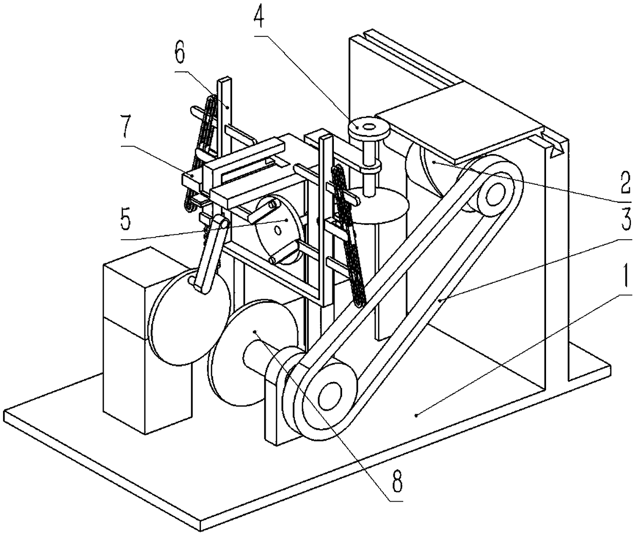
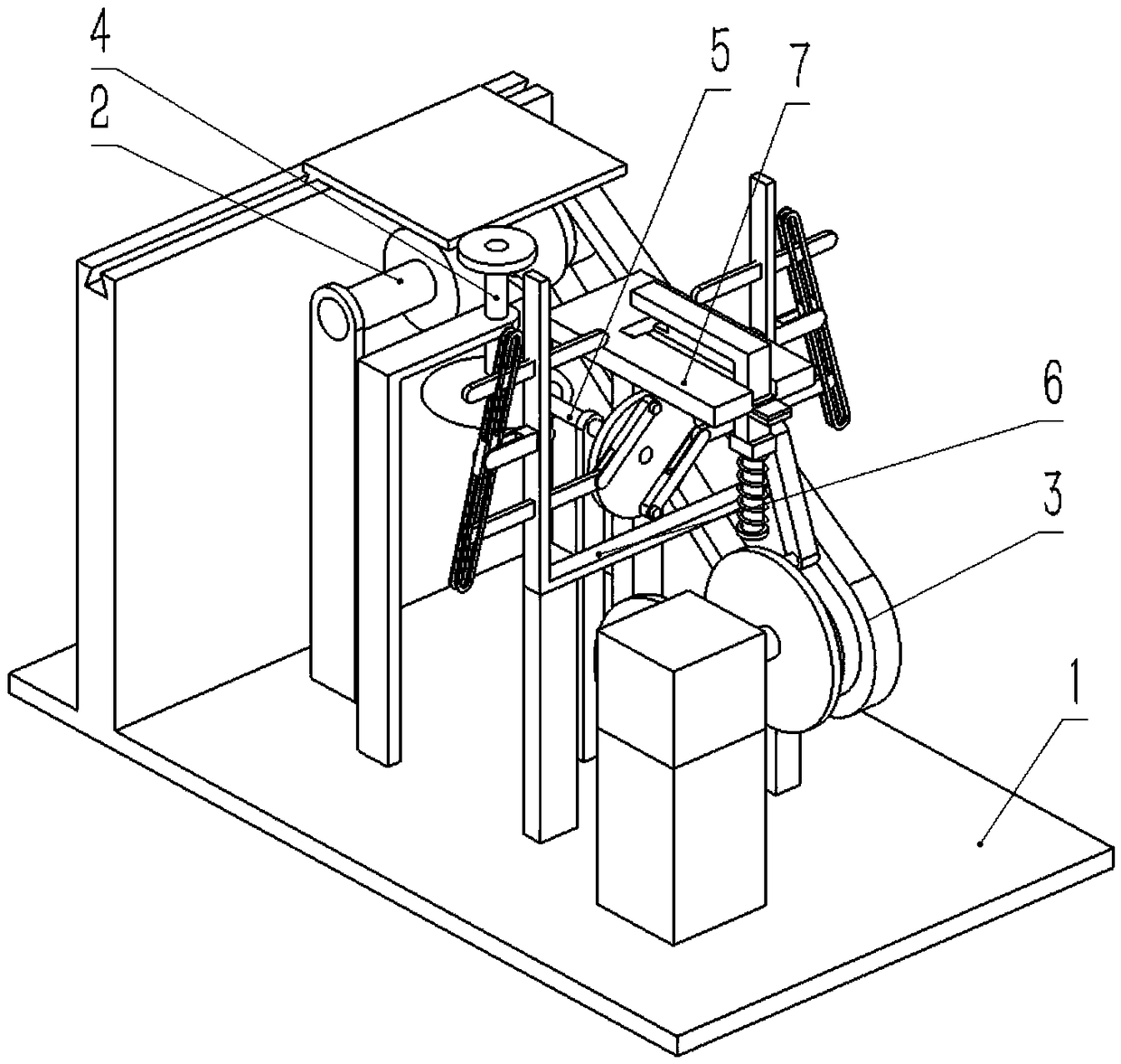
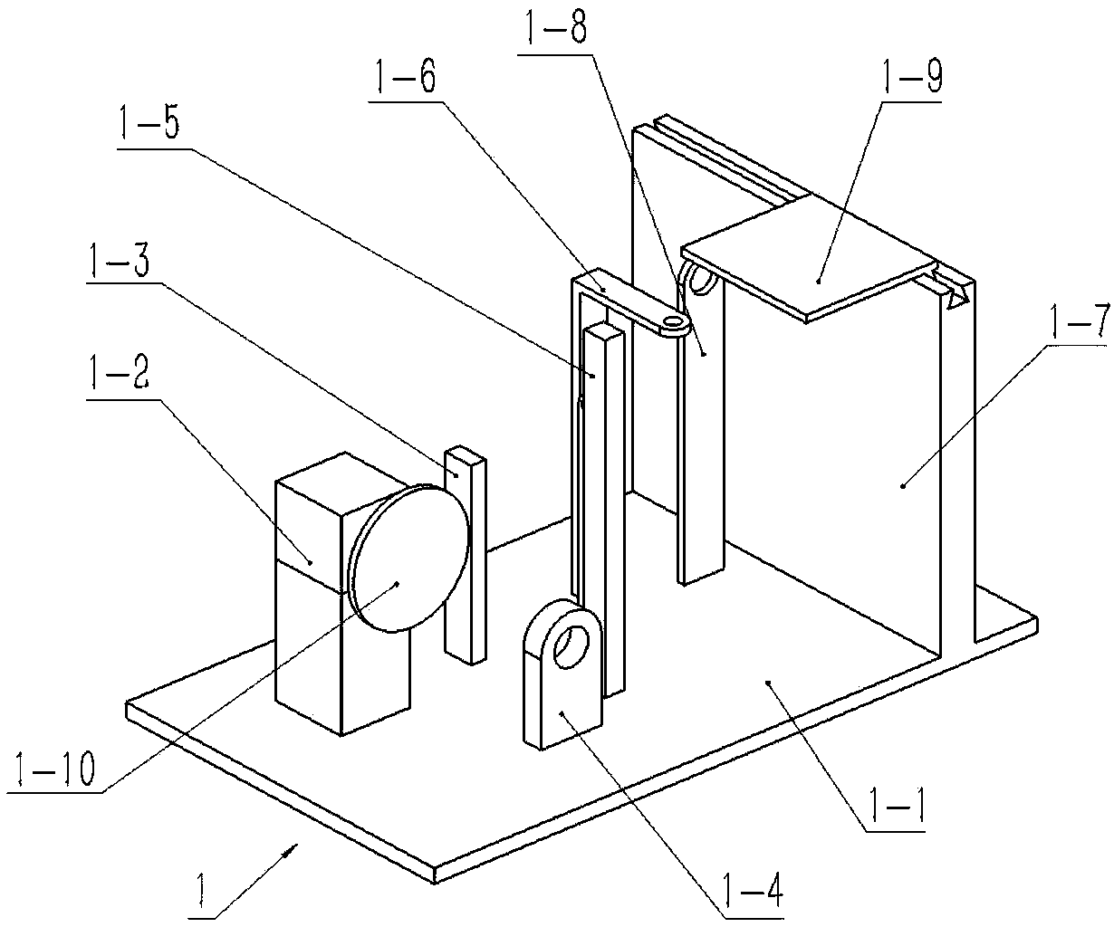
[0036] Combine below Figure 1-16Describe this embodiment, an Internet router network cable interface processing equipment, including a chassis assembly 1, a cylindrical roller assembly 2, a synchronous belt 3, a secondary transmission assembly 4, a lateral input assembly 5, and a push rod assembly 6. Compression rod assembly 7 and roller transmission assembly 8. The chassis assembly 1 includes a bottom plate 1-1, a motor 1-2, a push rod assembly fixing rod 1-3, and a roller transmission rotating plate 1-4. , pressure rod combination fixed rod 1-5, secondary transmission rotating rod 1-6, slide plate 1-7, cylindrical roller rotating rod 1-8, rack plate 1-9, input gear 1-10 and horizontal input rotating rod Rod 1-11, the rack plate 1-9 includes a rack plate body 1-9-1, a trapezoidal slider 1-9-2 and a sliding column 1-9-3, and the sliding column 1-9-3 Welded on the middle end of the rack plate body 1-9-1, the trapezoidal slider 1-9-2 is fixedly connected to the right end of th...

specific Embodiment approach 2

[0049] Combine below Figure 1-16 Describe this embodiment, this embodiment will further explain Embodiment 1, the annular chute 2-4 is an annular closed structure, so that the sliding column 1-9-3 can reciprocate in the annular chute 2-4, which is transformed into The reciprocating motion of the sliding column 1-9-3 moving back and forth laterally, drives the rack plate body 1-9-1 to move through the sliding column 1-9-3, and drives the secondary transmission through the rack plate body 1-9-1 The movement of the straight teeth 4-1 drives the movement of the secondary transmission shaft 4-2 through the secondary transmission straight teeth 4-1, thereby driving the movement of the secondary transmission bevel teeth 4-3, through the secondary transmission bevel teeth 4-3 and The transmission of the transverse bevel gear 5-5 drives the transverse input shaft 5-4 to rotate, thereby driving the transverse runner 5-1 to rotate back and forth.

specific Embodiment approach 3

[0050] Combine below Figure 1-16 This embodiment will be described. This embodiment will further describe the first embodiment. The depth of the rectangular groove I7-1-1 is smaller than the depth of the rectangular groove II7-1-2, which is convenient for pressing the metal sheet.

[0051] An Internet router network cable interface processing equipment of the present invention, its working principle is: when processing, place the iron piece in the rectangular slot I7-1-1, press the button switch SB1 to make the motor 1-2 energized and rotate, press the bar The initial position of the connecting rod 7-3 is at the highest point of the input gear 1-10. When the input gear 1-10 drives the pressing rod connecting rod 7-3 to move to 1 / 4 stroke, the up stroke terminal 7-4 and the down stroke The stroke terminal 7-5 is disengaged, and the stroke normally closed switch SQ1 connected between the upper stroke terminal 7-4 and the lower stroke terminal 7-5 is closed, so that the motor 1-...


PUM


Abstract

The invention relates to machining equipment, in particular to internet router reticle interface machining equipment which can conduct one-time molding machining on square metal sheets in reticle interface comprising USB types. The internet router reticle interface machining equipment comprises a chassis combining body, a cylindrical roller combining body, a synchronous belt, a two-stage transmission combining body, a transverse input combining body, a push rod combining body, a pressing rod combining body and a roller transmission combining body; a rack plate body and a sliding column can beused for achieving linkage of the cylindrical roller combining body and the two-stage transmission combining body; when a pressing rod connecting rod is rotated from the lowest point of an input gearto the highest point of the input gear, the pressing rod connecting rod vertically and upwards moves to drive a pressing rod to move upwards to enable the pressing rod to not extrude the metal sheetsany more; and an annular sliding groove is of an annular closed structure, so that reciprocating motion of the sliding column in the annular sliding groove can be converted into reciprocating motion of transverse front-and-back motion of the sliding column, and then a transverse rotating wheel is driven to do reciprocating rotation.

Description

technical field [0001] The invention relates to a processing device, in particular to an Internet router network cable interface processing device. Background technique [0002] For example, the patent No. CN201710956952.4 is an Internet router network cable interface processing equipment, including a body, a first mold, a card slot, a second mold and a slide rail, a support block is installed at one end of the body, and the inside of the support block is installed There is a hydraulic oil cylinder, a cross bar is installed horizontally on the top of the first transmission shaft, a storage compartment is installed on the side of the cross bar away from the first transmission shaft, a turntable is installed on the top of the body, and a turntable is installed around the top of the turntable. Working positions are evenly installed, and a first mold and a second mold are respectively installed inside the inner cavity. The present invention is equipped with a slide rail and a s...

Claims


Application Information

Patent Timeline
IPC IPC(8): B30B1/10B30B15/14B21D22/02
CPCB21D22/02B30B1/10B30B15/148
Inventor 张欣欣
Owner 日照法桐信息技术有限公司
Learn More