Wheel and running equipment with same

A wheel and equipment technology, applied in the field of wheels and walking equipment with the wheels, can solve problems affecting the safety and life of use, poor environmental adaptability, tire burst or damage, etc., achieve reliable pulse continuous rotation, and improve motion stability Effect

Active Publication Date: 2018-10-16
苏冀
View PDF4 Cites 5 Cited by
  • Summary
  • Abstract
  • Description
  • Claims
  • Application Information

AI Technical Summary

Problems solved by technology

Due to the limitation of its material, when the temperature rises significantly during driving, it will directly affect the safety and life of use; in t

Method used


Image

  • Wheel and running equipment with same
  • Wheel and running equipment with same
  • Wheel and running equipment with same

Examples


Embodiment 1

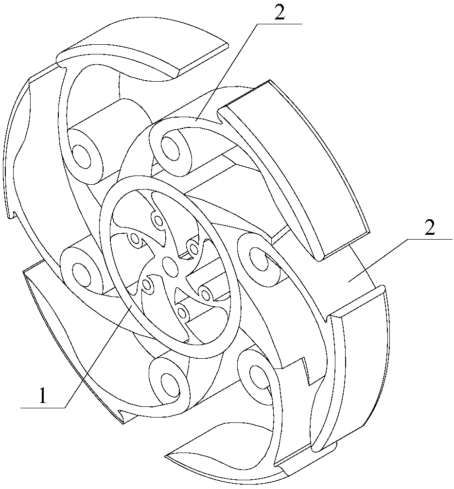
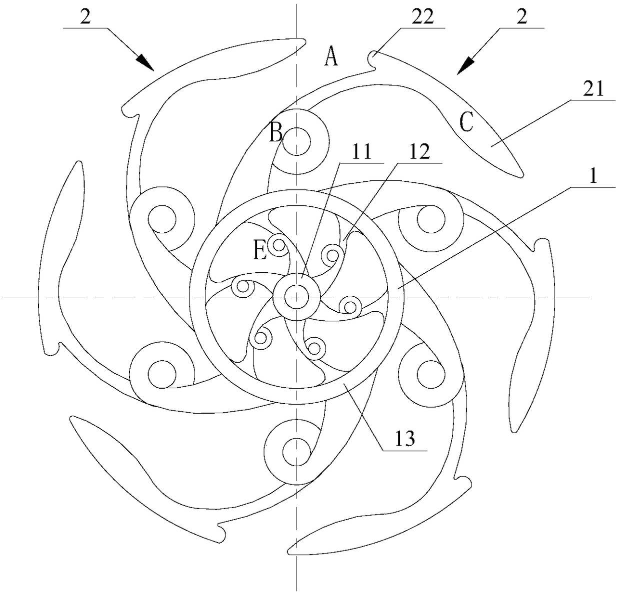
[0039] See figure 1 with figure 2 ,among them, figure 1 Is a three-dimensional schematic diagram of the wheel of this embodiment, figure 2 The front view of the wheel.

[0040] The wheel mainly includes a hub 1 adapted to a rotating shaft (not shown in the figure) of walking equipment and an elastic support 2, and a plurality of elastic supports 2 are evenly distributed on the outer peripheral surface of the hub 1 in a circumferential direction. Here, the multiple elastic support members 2 have both the functions of the spokes and rim of a traditional wheel, and the outer tire is eliminated based on its own rigidity and flexibility.

[0041] As shown in the figure, the body of the elastic support member 2 extends outward to form an end outer arc section 21. The outer arc sections 21 of a plurality of elastic support members 1 are arranged at intervals in the circumferential direction, and two adjacent outer arc sections form Discontinuous opening area A. And each outer arc segme...

Embodiment 2

[0051] The difference between this solution and the first embodiment lies in the change in the structure of the hub and the addition of the optional adapter 14, which can be applied to the temporary replacement function of another walking device. See Figure 5 This figure shows a schematic diagram of the assembly relationship of the wheel in another use state of this embodiment. In order to clearly show the difference and connection between this embodiment and Embodiment 1, the same functional components in the figure are indicated by the same symbols.

[0052] Specifically, the inner ring portion 11 and a plurality of inner elastic support portions 12 are integrated into one body, and can be detachably connected with the outer ring portion 13, such as threaded connection or snap connection; that is, the inner ring portion 11 and the inner elastic support portion The part 12 can be detached from the outer ring part 13, wherein the optional adapter 14 can also be detachably connect...

Embodiment 3

[0055] The difference between this solution and Embodiment 1 or Embodiment 2 is that the wheel is additionally provided with a rubber coating layer 3, which covers a plurality of elastic support members 2, and the overall outer contour is a continuous disc shape, forming Whole coating. See Figure 8 This figure is a schematic diagram of the wheel described in the solution. In order to clearly show the difference and connection between this embodiment and the first and second embodiments, the same functional components in the figure are indicated by the same symbols.

[0056] That is to say, the gap (opening) is connected by flexible materials, and the appearance of the wheel is like a traditional wheel. That is, the rigid and flexible characteristics of the disc structure are composed of an elastic skeleton and a highly elastic covering material. The circle is coherent, further improving its smooth operation. Here, the rubber coating layer 3 can be made of foamed silicon rubber ...


PUM


Abstract

The invention discloses a wheel. A hub of the wheel is adaptive to a rotating shaft of running equipment; a plurality of elastic supporting pieces are uniformly distributed on the peripheral surface of the hub in the circumferential direction; bodies of the elastic supporting pieces extend outwards to form end part external circular arc sections; the external circular arc sections of the pluralityof elastic supporting pieces are arranged in sequence in a spaced manner in the circumferential direction and have concentric and isodiametric convex circular arc surfaces; the elastic supporting pieces have stress deformation areas and stress position changing areas and are configured in such a way that the stress deformation areas are positioned at the middle sections of the main bodies; the direction of deformation stress generated under an outside force in the moving process tends to be consistent with the tangential direction of the rotation of the hub so that an acting force for pushingthe hub to rotate is formed during releasing the deformation stress; and the external circular arc sections are the stress position changing areas and can generate displacements with the deformations. According to the scheme, as the traditional rigid structure is transformed into rigid and soft combined structure, and an outer tire is eliminated, good running performance can be obtained, and theinfluence of a severe use environment on the service life of the wheel can be effectively avoided. The invention further provides running equipment with the wheel.

Description

Technical field [0001] The invention relates to the technical field of mechanical wheels, in particular to a wheel and walking equipment with the wheel. Background technique [0002] As we all know, the traditional wheel pays attention to the continuity of rolling, which obtains the rolling friction force through the ring-closed rigid rim. Most of the existing wheels are composed of a rim and a hub, spokes and a tire cover mounted on the outer periphery of the rim. Among them, the hub forms a rigid disc-shaped structure through the spokes and the rim, and the tire absorbs shock and vibration loads during the bearing process. . [0003] The existing tires of automatic vehicles or motor vehicles mainly include two structural forms, one is a pneumatic rubber tire, and the other is a solid rubber or silicon rubber tire. Due to the limitation of its material, when the temperature rises significantly during driving, it will directly affect the safety and life of use; in the case of rel...

Claims


Application Information

Patent Timeline
IPC IPC(8): B60B9/00B60B9/26
CPCB60B9/00B60B9/005B60B9/26
Inventor 苏冀
Owner 苏冀
Why Eureka
Try Eureka