Large-sized seagoing vessel berth stabilizing device

A technology of anti-rolling device and bed, which is applied in the direction of the bed in the engine room, reducing the movement of the ship through the displacement, and the living quarters. It can solve the problems of discounting work efficiency, single anti-rolling principle, and affecting the sleep quality of the crew, and achieves a good shock-absorbing effect. Effect

Inactive Publication Date: 2018-10-16
WUHAN UNIV OF TECH
View PDF8 Cites 4 Cited by
  • Summary
  • Abstract
  • Description
  • Claims
  • Application Information

AI Technical Summary

Problems solved by technology

As a free body floating in the water, the ship will produce serious deep motion, rolling and pitching motion under the action of external wind, waves and currents, which seriously affects the sleep quality of the crew and greatly reduces their work efficiency. In recent years, in order to To reduce the vibration amplitude of the bed of a large sea-going ship and improve a good rest environment for the crew, people have designed many anti-rolling devices, such as setting flexible springs at the bottom of the bed, but due to the singleness of the anti-rolling principle, the The effect is not ideal

Method used


Image

  • Large-sized seagoing vessel berth stabilizing device
  • Large-sized seagoing vessel berth stabilizing device
  • Large-sized seagoing vessel berth stabilizing device

Examples


Embodiment Construction

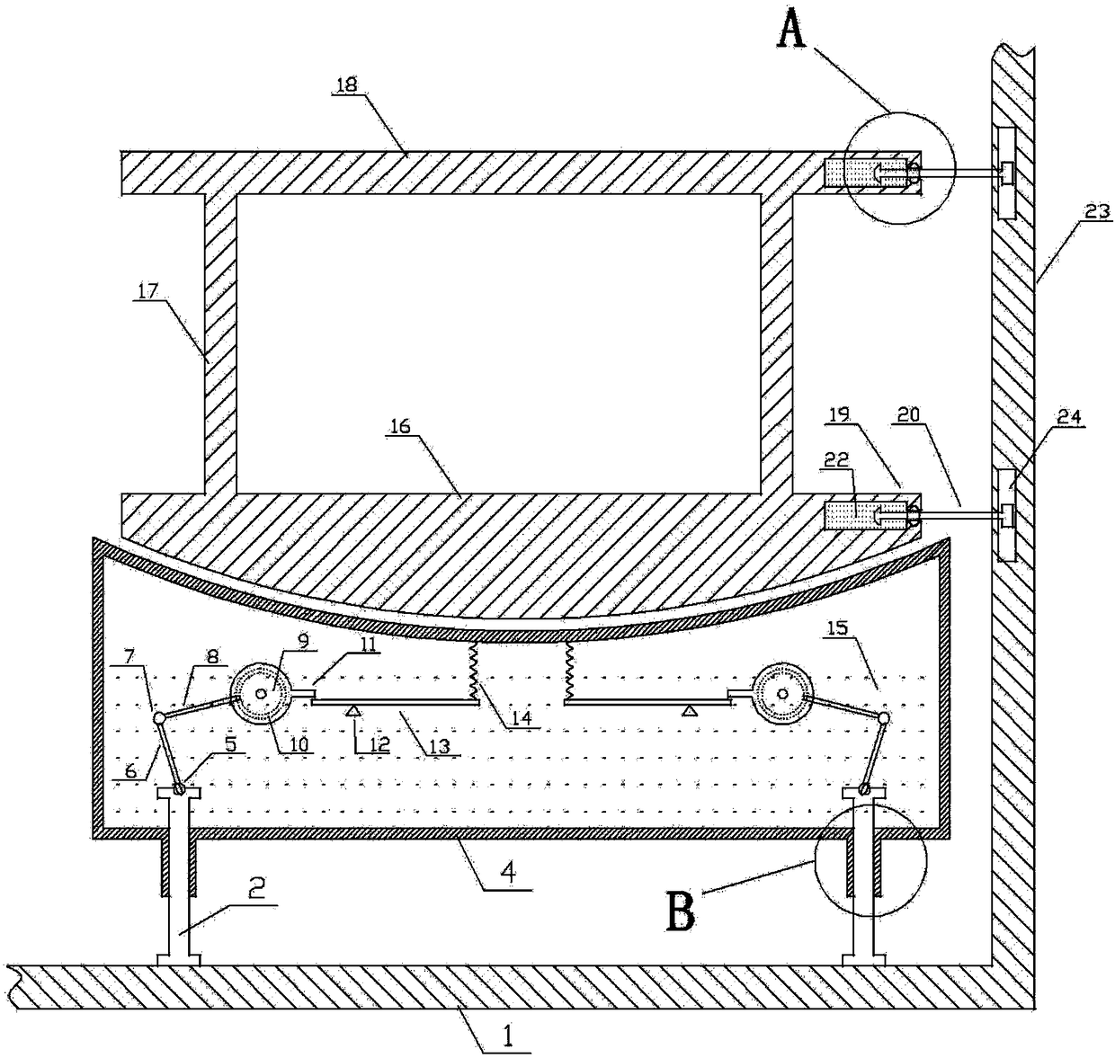
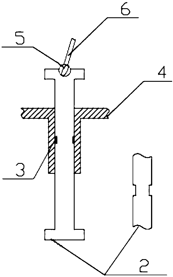
[0023] Below through embodiment, in conjunction with accompanying drawing, the technical scheme of the present invention is described further specifically, as shown in the figure figure 1 and figure 2 As shown, the vertical guide post 2 is in free contact with the deck ground 1 of the ship, and a groove is engraved in the middle of the vertical guide post 2, and a sealing gasket 3 is arranged in this area, and the vertical guide post 2 is nested in the bottom of the liquid tank 4 vertically downward In the protruding tubular structure, in order to ensure that the vertical guide column 2 does not leak liquid when it moves vertically, the upper and lower ends of the vertical guide column 2 are provided with limiting structures protruding to both sides to prevent the vertical guide column from leaking. 2 is separated from the liquid tank 4 structure, and the upper end of the vertical guide column 2 is connected with the crank 6 through the universal joint A5 to ensure that the c...


PUM


Abstract

The invention provides a large-sized seagoing vessel berth stabilizing device. The large-sized seagoing vessel berth stabilizing device comprises a liquid tank arranged at the bottom of a berth; the bottom of the liquid tank is connected with the floor of a deck through a plurality of vertical guide columns; the side edge of the berth is connected with a transverse bulkhead in a floating manner; aplurality of tubular structures for the vertical guide columns to penetrate through are formed in the bottom of the liquid tank; the upper ends of the vertical guide columns are connected with the top of a cavity of the liquid tank through a crank vibration structures and flexible springs; and the liquid tank is filled with viscous liquid. According to the large-sized seagoing vessel berth stabilizing device, through vertical motions of the vertical guide columns, rotations of the crank structures, circular discs and levers, disturbance of liquid and compression of the flexible springs, outside vibration force is gradually converted into kinetic energy of the structures, the internal energy of the liquid and elastic potential energy of the springs so as to reduce power response of the berth caused by deep sinking motion of a hull; and therefore, the shaking amplitude of the berth can be reduced; after the outside vibration force disappears, each mechanism returns to the original position under effects of the gravitational potential energy of the liquid and the elastic potential energy of the springs so that the device can bear an effect of the outside vibration force again.

Description

technical field [0001] The invention relates to the field of anti-rolling in a local area of ​​a ship hull, in particular to a bed anti-rolling device for a large sea-going ship. Background technique [0002] With the improvement of the economic level, more and more goods are transported to all parts of the world by large cargo ships. As a free body floating in the water, the ship will produce serious deep motion, rolling and pitching motion under the action of external wind, waves and currents, which seriously affects the sleep quality of the crew and greatly reduces their work efficiency. In recent years, in order to To reduce the vibration amplitude of the bed of a large sea-going ship and improve a good rest environment for the crew, people have designed many anti-rolling devices, such as setting flexible springs at the bottom of the bed, but due to the singleness of the anti-rolling principle, the The effect is not ideal. Therefore, it is necessary to design a bed ant...

Claims


Application Information

Patent Timeline
IPC IPC(8): B63B29/10B63B39/03
CPCB63B29/10B63B39/03
Inventor 胡勇陈兴怖王旭阳徐敬博许威
Owner WUHAN UNIV OF TECH
Why Eureka
Try Eureka