
In-orbit spacecraft internal device installing structure capable of quickly being disassembled and turned over

A technology of internal equipment and installation structure, applied in the field of spacecraft, can solve the problems of multi-layout of instruments and equipment, influence of instruments and equipment, dispersion, etc., and achieve the effect of simple structure, avoiding pollution, and large load capacity

Active Publication Date: 2018-10-16
BEIJING INST OF SPACECRAFT SYST ENG
View PDF5 Cites 2 Cited by
  • Summary
  • Abstract
  • Description
  • Claims
  • Application Information

AI Technical Summary

Problems solved by technology

[0004] (1) The metal frame structure is only suitable for concentrated loads with a large installation mass. There are many instruments and equipment inside the sealed cabin and the layout is scattered, and the adaptability of the frame structure is poor. It is beneficial to the life and activities of people in the cabin, and the pollutants of human life are directly in contact with the equipment, which is easy to affect the equipment
[0005] (2) Plate structure (patent ZL201218002884.6, a lightweight equipment installation structure inside the sealed cabin of a spacecraft), the internal structure of Tiangong-1 in China is a plate structure, but the plate structure is the same as the metal frame structure, and the structural instruments and equipment are exposed to In the sealed cabin, the practicability and aesthetics are poor

Method used


Image

  • In-orbit spacecraft internal device installing structure capable of quickly being disassembled and turned over
  • In-orbit spacecraft internal device installing structure capable of quickly being disassembled and turned over
  • In-orbit spacecraft internal device installing structure capable of quickly being disassembled and turned over

Examples


Embodiment Construction

[0027] Below in conjunction with accompanying drawing, the present invention is described in further detail:

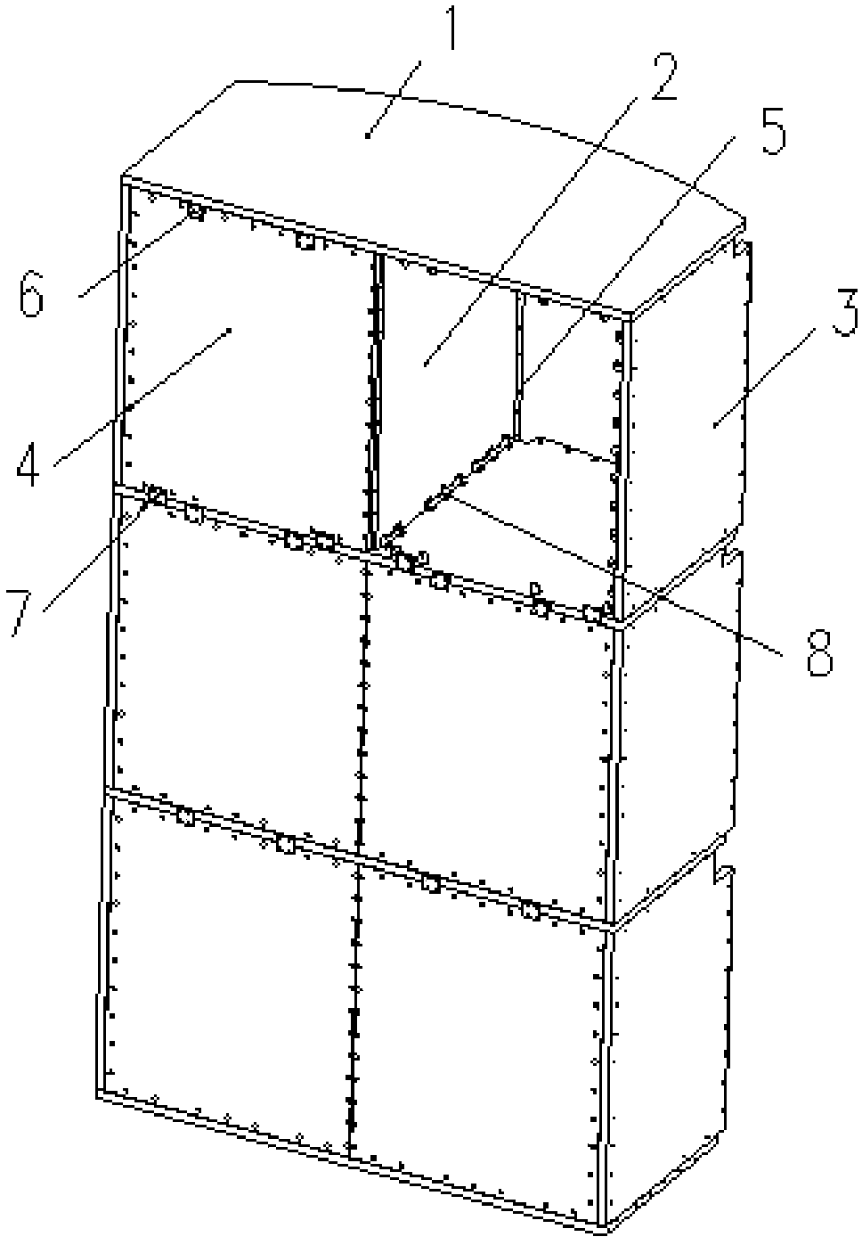
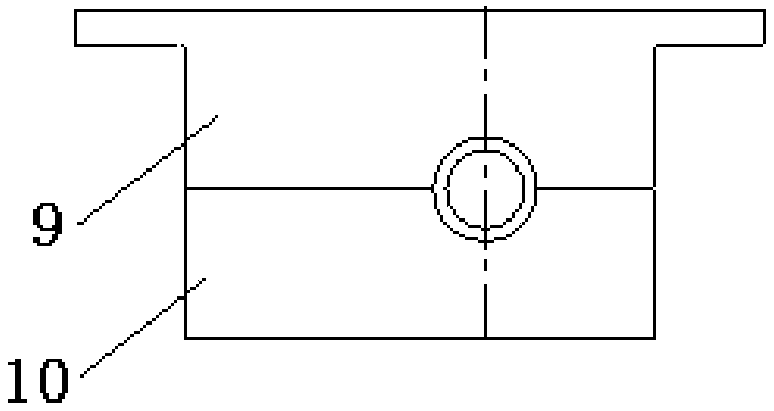
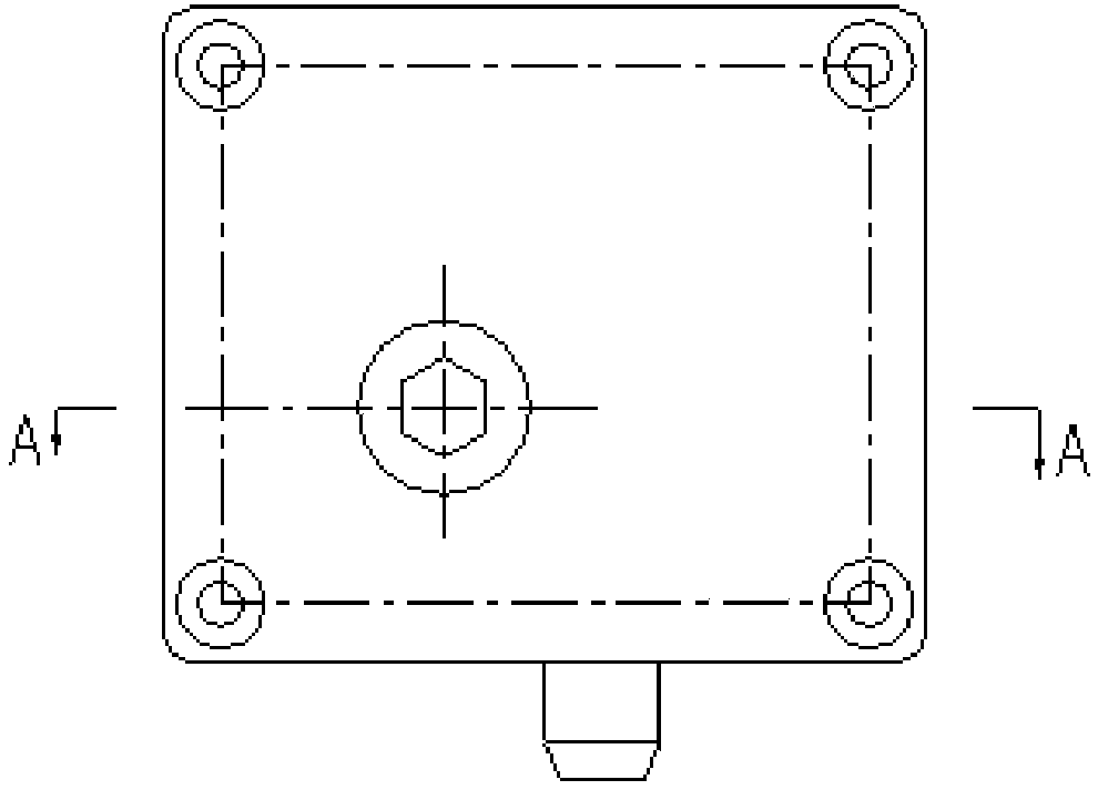
[0028] figure 1 It is a schematic diagram of the installation structure of the spacecraft internal equipment that can be quickly disassembled and turned over in orbit according to the present invention. Such as figure 1 As shown, the internal equipment installation structure of the spacecraft that can be quickly disassembled and flipped on orbit includes: several horizontal plates 1, several middle vertical plates 2, several side vertical plates 3, several cover plates 4 and several vertical beams 5 . Specifically, the number of horizontal boards 1, middle vertical boards 2, side vertical boards 3 and cover boards 4 can be selected arbitrarily as required. The quantity of the horizontal plate 1 shown in Fig. 2 is 3, the quantity of the middle vertical plate 2 is 3, the quantity of the side vertical plate 3 is 6, the quantity of the cover plate 4 is 6, the horizonta...


PUM


Abstract

The invention discloses an in-orbit spacecraft internal device installing structure capable of quickly being disassembled and turned over. The in-orbit spacecraft internal device installing structurecomprises a plurality of horizontal plates, a plurality of middle vertical plates, a plurality of side vertical plates, a plurality of cover plates and a plurality of vertical beams. The plurality ofhorizontal plates are arranged side by side, every two adjacent horizontal plates are connected with the middle vertical plates, and every two adjacent horizontal plates are equally divided into two space units by the middle vertical plates, the side vertical plates are connected to the side faces of the space units, and the cover plates are connected to the front faces of the space units. One side of each middle vertical plate is connected with the corresponding vertical beam, and one side of each side vertical plate is connected with the corresponding vertical beam. The vertical beams are connected with connecting frames in a sealed cabin. The in-orbit spacecraft internal device installing structure capable of quickly being disassembled and turned over has the advantages of large installation space, attractive appearance, safety and being capable of being quickly disassembled and repaired in orbit.

Description

technical field [0001] The invention belongs to the field of spacecraft, and in particular relates to a spacecraft internal equipment installation structure that can be quickly disassembled and turned over on orbit. Background technique [0002] The interior of the spacecraft airtight cabin needs to be installed with instruments and equipment for on-orbit support and space testing, and it is also necessary to provide space for astronauts to work and live. Therefore, it is necessary to design an internal structure capable of installing instruments and equipment. The internal structure needs to have a large load, light weight In addition, when it comes to human on-orbit operations, this type of structure also needs to have good ergonomics requirements. [0003] At present, the main forms of the internal structure of the spacecraft airtight cabin at home and abroad are as follows: [0004] (1) The metal frame structure is only suitable for concentrated loads with a large insta...

Claims


Application Information

Patent Timeline
Patent Type & Authority Applications(China)
IPC IPC(8): B64G1/66
CPCB64G1/66
Inventor 陈燕施丽铭姜超张玲张啸雨张琳周志勇成志忠许焕宾陈茹孙蕾臧晓云
Owner BEIJING INST OF SPACECRAFT SYST ENG
Learn More