A cartridge type pressure compensating valve

A pressure-compensating, plug-in technology, applied in the direction of fluid pressure actuators, valve devices, multi-way valves, etc., can solve the problems of large volume, bulky, inconvenient integration, etc., and achieve low cost, compact structure, and spare parts little effect

Active Publication Date: 2019-12-20
日照首跃科技服务有限公司
View PDF5 Cites 1 Cited by
  • Summary
  • Abstract
  • Description
  • Claims
  • Application Information

AI Technical Summary

Problems solved by technology

However, the pressure compensating valves currently on the market are either a pressure compensating valve composed of a plurality of discrete parts combined with a multi-way reversing valve in the form of a casting, or a single plate connection or stacked pressure compensating valve , the above forms of pressure compensation valves have the disadvantages of being inconvenient for cartridge integration, too large, and heavy, and are not suitable for application in hydraulic systems integrated with cartridge valves.

Method used


Image

  • A cartridge type pressure compensating valve
  • A cartridge type pressure compensating valve
  • A cartridge type pressure compensating valve

Examples


Embodiment Construction

[0014] The present invention will be further described in detail below in conjunction with the accompanying drawings and embodiments.

[0015] Such as Figure 1~3 Shown is a preferred embodiment of the present invention.

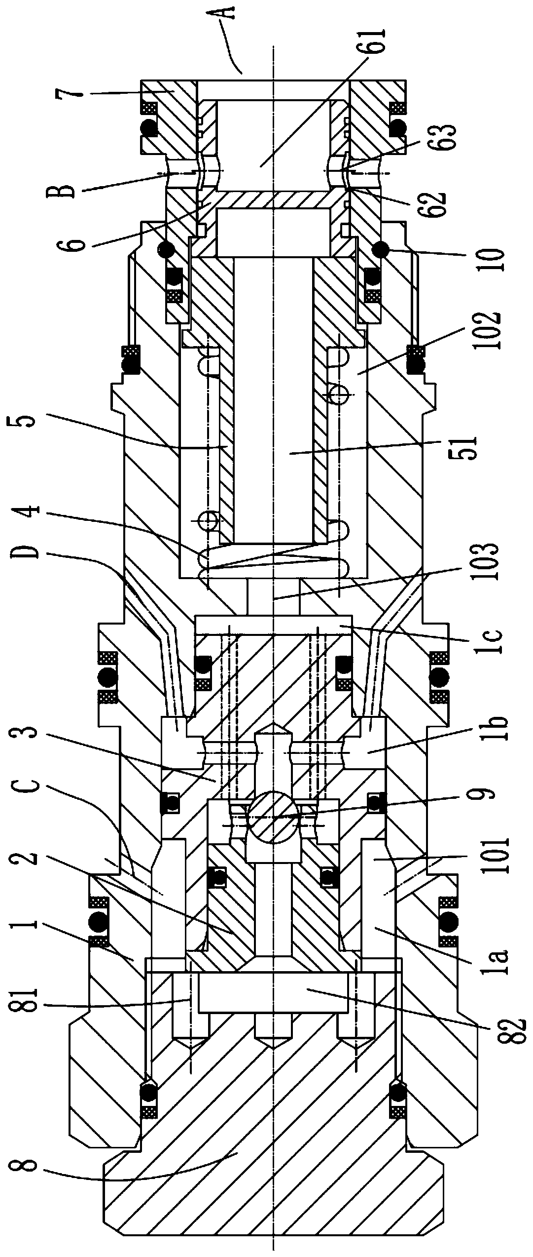
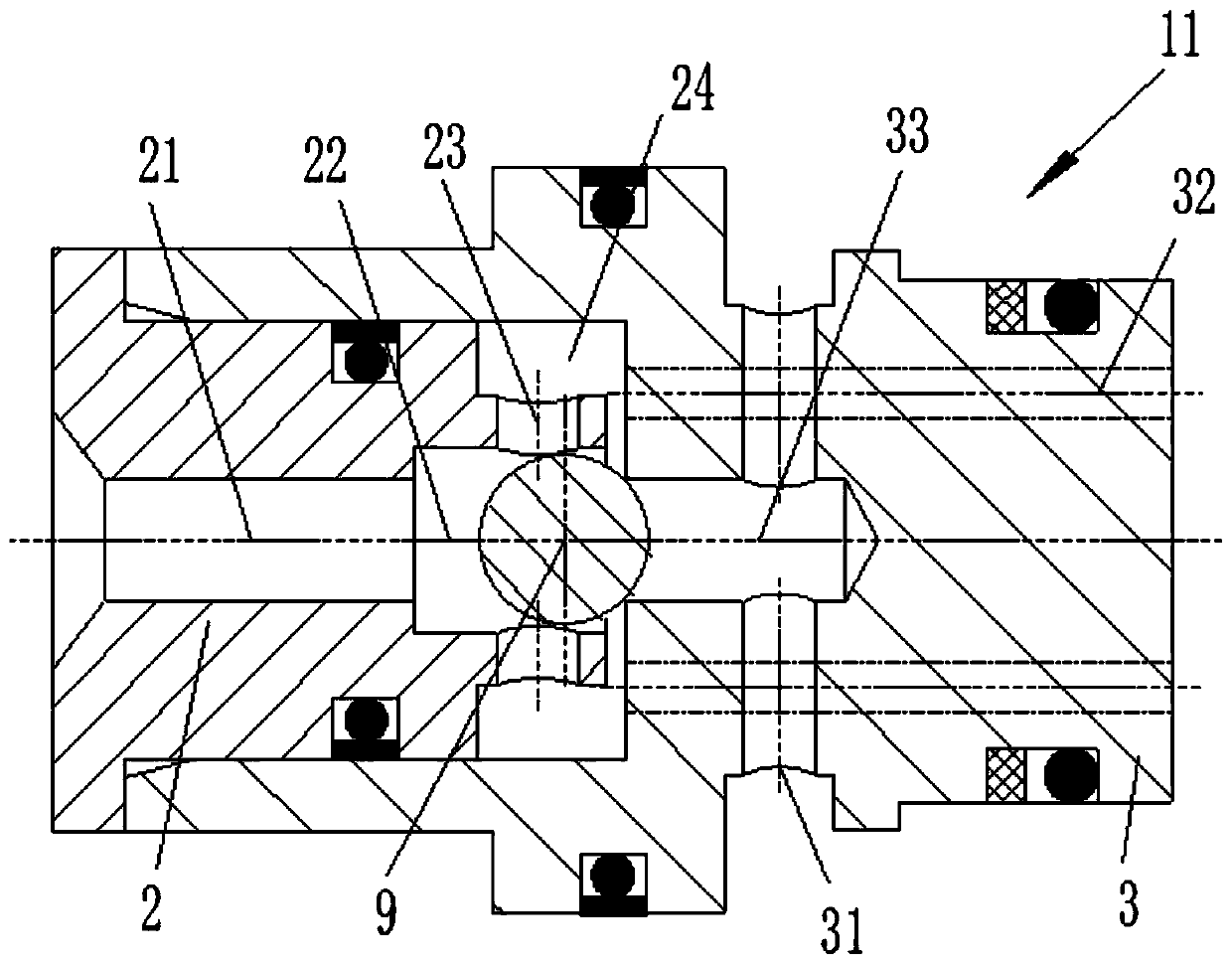
[0016] A cartridge pressure compensation valve includes a valve body 1 , a shuttle valve assembly 11 , a valve sleeve 7 , a valve core 6 , a spring seat 5 , a spring 4 and a screw plug 8 .

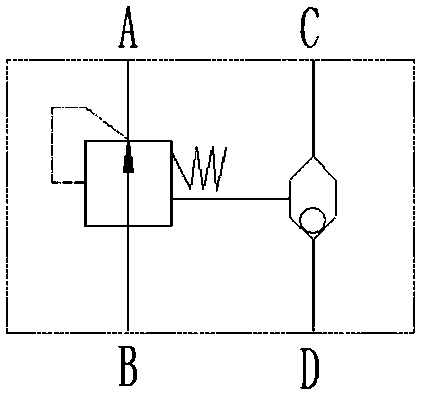
[0017] The valve body 1 is provided with a first installation chamber 101 and a second installation chamber 102 along the axial direction, and a first pressure oil port C and a second pressure oil port D communicating with the first installation chamber 101 are provided on the side wall , the valve body 1 is further provided with a first through hole 103 communicating with the first installation cavity 101 and the second installation cavity 102 .

[0018] The shuttle valve assembly 11 is arranged in the first installation chamber 101 and divides the first installation ...


PUM


Abstract

The invention relates to a plug-in pressure compensation valve, which is characterized in that it includes a valve body, a shuttle valve assembly, a valve sleeve, a valve core, a spring seat, a spring and a screw plug, and the valve body is provided with a first pressure oil port, a second Two pressure oil ports, the first installation cavity, the second installation cavity and the first flow hole, the shuttle valve assembly is installed in the first installation cavity, the valve sleeve is provided with the third pressure oil port and the fourth pressure oil port, the valve The core is slidingly arranged in the valve sleeve, and the spring and the spring seat are arranged in the second installation chamber to offset against the valve core. The invention has a plug-in design, compact structure, low processing cost and can realize the pressure compensation function.

Description

technical field [0001] The invention belongs to the technical field of valves, in particular to a plug-in pressure compensation valve. Background technique [0002] Pressure compensation technology is widely used in hydraulic systems. During use, the main oil circuit is connected to the oil inlet port of the pressure compensation valve, and the oil outlet port of the pressure compensation valve is connected to the oil inlet port of the proportional directional control valve. The spring chamber of the compensation valve adjusts the pressure difference between the oil inlet port and the working oil port of the proportional directional control valve through the pressure compensation valve, and then realizes that the output flow of the working oil port of the proportional directional control valve is constant and has nothing to do with the change of the working load. However, the pressure compensating valves currently on the market are either a pressure compensating valve compo...

Claims


Application Information

Patent Timeline
Patent Type & Authority Patents(China)
IPC IPC(8): F15B13/02
CPCF15B13/02F16K11/0716F15B2013/004
Inventor 邹茶香其他发明人请求不公开姓名
Owner 日照首跃科技服务有限公司
Why Eureka
Try Eureka