Linear guide rail

A technology of linear guide rails and guide rails, applied in the field of linear guide rails, can solve the problems of increased cost, increased maintenance times, shortened service life of rolling elements, etc., and achieves the effects of reduced maintenance costs, increased operating speed, and long lubrication time

Pending Publication Date: 2018-10-16
LISHUI JIEXIANG TECH CO LTD
View PDF9 Cites 7 Cited by
  • Summary
  • Abstract
  • Description
  • Claims
  • Application Information

AI Technical Summary

Problems solved by technology

[0004] 1. When the linear guide rail is working, the slider slides circularly on the guide rail through the rolling elements, and the two rolling elements contact each other to form a circular rolling. The direction of motion between the contact positions of the two rolling elements is opposite, so that the two rolling elements exist. Mutual friction, friction is easy to generate heat, which affects the running speed of the rolling elements, long-term friction causes the wear of the rolling elements, shortens the service life of the rolling elements, frequently increases the maintenance frequency, and increases the cost
[0005] 2. The linear guide rail will be installed in different directions according to different working situations. Due to the installation and placement in different directions, the lubricating oil in the lubricating oil chamber cannot satisfy the oil supply and lubrication in each direction, which will affect the normal operation of the linear guide rail. When the lubricating oil is used, only the bottom has lubricating oil, and the lubricating oil cannot reach the upper part, so that it cannot reach the circulating raceway between the guide rail and the slider, which affects the operation and lubrication of the linear guide rail.
[0006] 3. There is a gap between the slider and the guide rail in the linear guide rail. When the slider is covering the guide rail, it is easy for external tiny particles to enter the grooves on both sides of the guide rail during work. When the slider covers the guide rail again, the tiny particles enter The bead groove is easy to cause the rolling body between the slider and the guide rail to be stuck

Method used


Image

  • Linear guide rail
  • Linear guide rail
  • Linear guide rail

Examples


Embodiment Construction

[0063] The preferred embodiments of the present invention will be described in detail below in conjunction with the accompanying drawings, so that the advantages and features of the present invention can be more easily understood by those skilled in the art, so as to define the protection scope of the present invention more clearly.

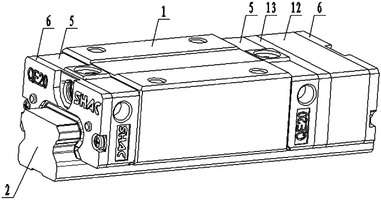
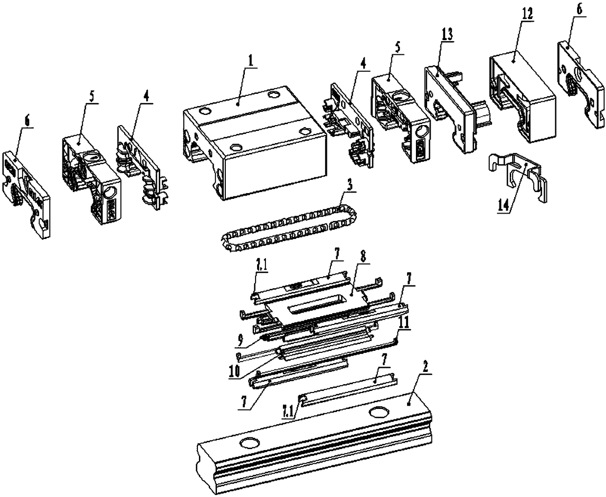
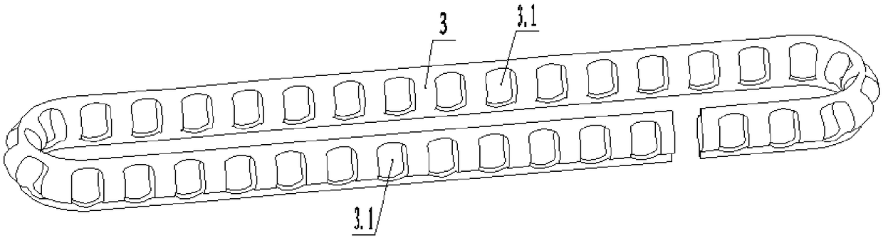
[0064] like Figure 1-11 As shown, the patent of the present invention provides a linear guide rail, including a slider 1, a guide rail 2, a rolling element, a rolling element chain 3, two inner loops 4, two outer loops 5, lubricating parts, and two dust covers 6 , the slider 1 is rotatably set on the guide rail 2 through the rolling element chain 3 and the rolling elements arranged in it, the left and right ends of the slider 1 are respectively fixed with an inner loop 4, and the rolling element chain 3 is inserted through the inner loop 4 In the circulation raceway formed between the slider 1 and the guide rail 2, the outer end of the inner cir...


PUM


Abstract

The invention provides a linear guide rail. The linear guide rail comprises a sliding block, a guide rail, a rolling body, a rolling body chain, two inner cycles, two outer cycles, a lubricating pieceand two dust covers. The sliding block is arranged on the guide rail in a rolling mode through the rolling body chain and the rolling body arranged in the rolling body chain. The inner cycles are fixedly arranged at the left end and the right end of the sliding block correspondingly. The rolling body chain is inserted in the space between the sliding block and the guide rail through the inner cycles to form an inner circulating roller way. The outer cycles are fixedly arranged at the outer ends of the inner cycles. One dust cover is fixedly arranged at the outer end of the outer cycle at theleft end. The lubricating piece is fixedly arranged at the outer end of the outer cycle at the right end. The other dust cover is fixedly arranged at the outer end of the lubricating piece. The linearguide rail is compact and stable in structure, the rolling body operates stably, the operating speed is increased, the lubricating time is kept long, and thus, maintenance is not needed for a long time, and the maintenance cost is reduced. The lubricating effect between the sliding block and the guide rail is good, the structure of an oil guide element enables lubrication to be achieved no matterin which way the linear guide rail is placed, and a dust-proof strip is provided with a big end and a small end and thus can be mounted correctly and conveniently.

Description

technical field [0001] The invention relates to the technical field of machinery, in particular to a linear guide rail. Background technique [0002] Linear guide rails, also known as line rails, slide rails, linear guide rails, and linear slide rails, are used in linear reciprocating motion applications, and can bear a certain torque, and can achieve high-precision linear motion under high load conditions. The function of linear guide rail motion is to support and guide the moving parts, and make reciprocating linear motion in a given direction. Linear guides are mainly used in mechanical structures with relatively high precision requirements. There is no intermediate medium between the moving elements and fixed elements of the linear guides, but rolling rolling elements. [0003] At present, the traditional linear guide has the following defects. [0004] 1. When the linear guide rail is working, the slider slides circularly on the guide rail through the rolling elements...

Claims


Application Information

Patent Timeline
Patent Type & Authority Applications(China)
IPC IPC(8): F16C29/04F16C29/08F16N1/00
CPCF16C29/04F16C29/082F16N1/00
Inventor 翁海龙叶卢炼汤超雄潘建鑫陈秀
Owner LISHUI JIEXIANG TECH CO LTD
Why Eureka
Try Eureka