Speed reducer protection device

A protection device, reducer technology, applied in the direction of transmission parts, mechanical equipment, belts/chains/gears, etc., can solve the problems of shortening the service life of the reducer, damage to the surface of the reducer, etc., to strengthen the buffer effect and prolong the service life. , the effect of preventing damage

Active Publication Date: 2018-10-16
ZHEJIANG IND & TRADE VACATIONAL COLLEGE
View PDF8 Cites 5 Cited by
  • Summary
  • Abstract
  • Description
  • Claims
  • Application Information

AI Technical Summary

Problems solved by technology

[0004] The purpose of the present invention is to provide a reducer protection device, which solves the problem tha...

Method used


Image

  • Speed reducer protection device
  • Speed reducer protection device
  • Speed reducer protection device

Examples


Embodiment Construction

[0039] The embodiments of the present invention will be described in detail below with reference to the accompanying drawings, but the present invention can be implemented in many different ways defined and covered by the claims.

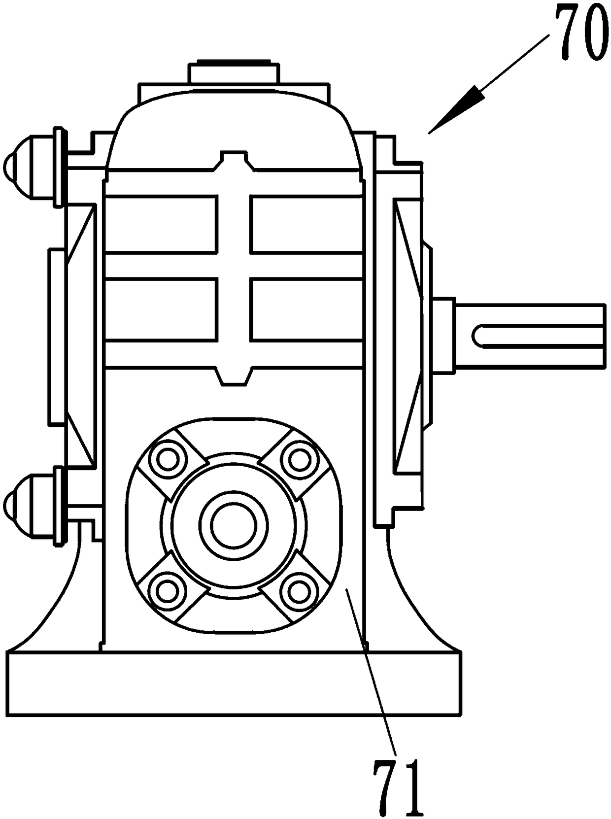
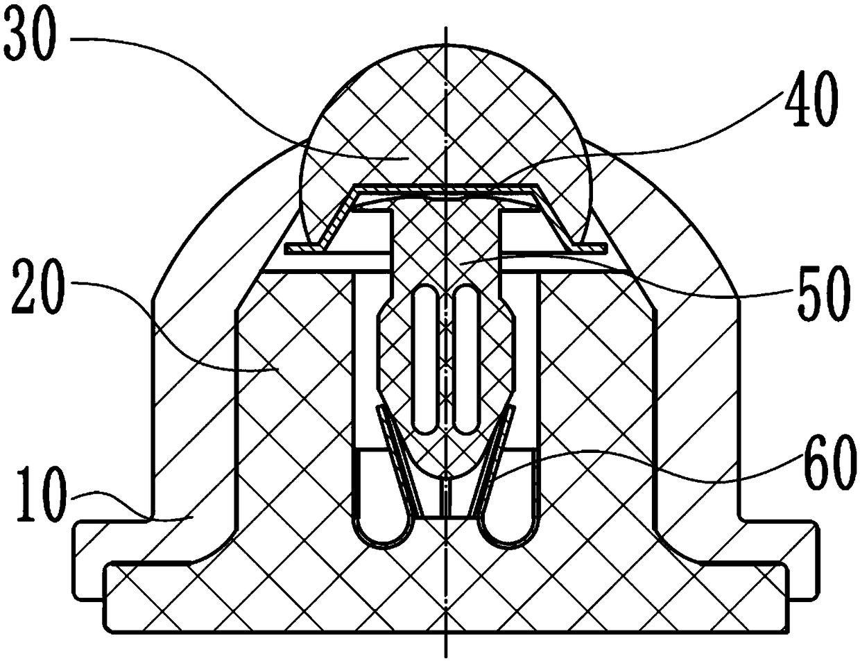
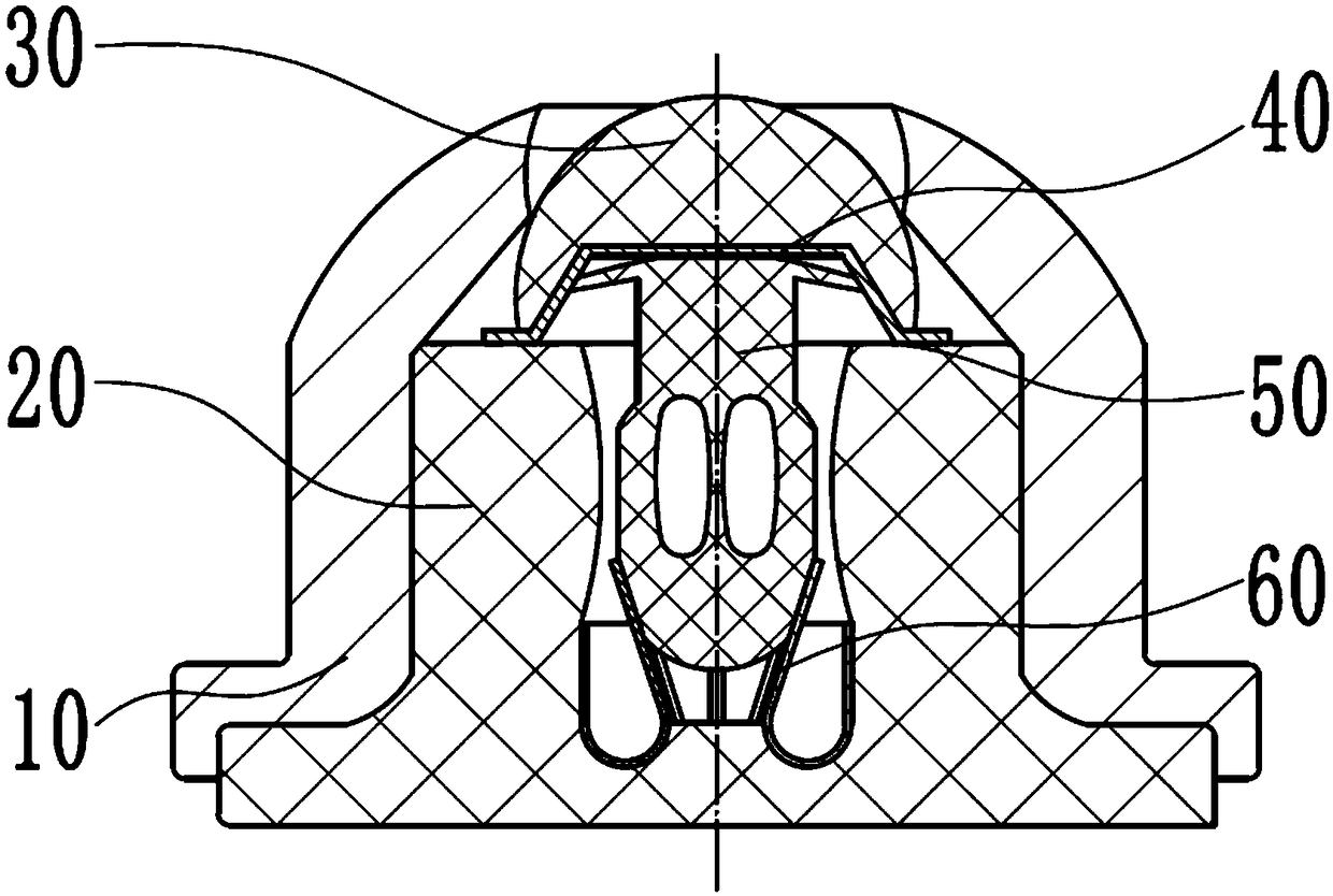
[0040] Refer below Figure 1 to Figure 10 The present invention is described further, as figure 1 with figure 2 A reducer protection device is shown, the protection device is glued on the outer surface of the reduction box body 71 of the reducer 70, wherein the protection device includes: a rubber base 20, a protective shell 10, and a pressure member 60 , bee wing elastic member 50, rubber body 30 and compression shell 40, the protective shell 10 is sleeved on the rubber base 20, the pressure bearing member 60 is installed in the rubber base 20, and the bee wing elastic The lower part of the member 50 is pressed against the pressure-bearing member 60, the upper part of the bee wing elastic member 50 protrudes from the upper end of the rubber base...


PUM


Abstract

The invention provides a speed reducer protection device which is glued to the outer surface of a reduction gearbox body of a speed reducer through glue. The protection device comprises a rubber base,a protection shell, a bearing part, a bee wing elastic part and a rubber body, the rubber base is sleeved with the protection shell, the bearing part installed in the rubber base, the lower portion of the bee wing elastic part abuts against the bearing part, the upper portion of the bee wing elastic part stretches out of the upper end face of the rubber base to extend upwards, the rubber body isplaced on the upper portion of the bee wing elastic part, and the rubber body penetrates through the upper portion of the protection shell to extend out of the protection shell. According to the speedreducer protection device, by adopting the structure, the surface of the speed reducer can be protected and prevented from being damaged, and therefore the service life of the speed reducer can be prolonged.

Description

technical field [0001] The invention belongs to the field of reducers, in particular to a protection device for a reducer. Background technique [0002] The reducer is generally used for low-speed and high-torque transmission equipment. The motor, internal combustion engine or other high-speed running power is used to achieve the purpose of deceleration through the gear with a small number of teeth on the input shaft of the reducer and the large gear on the output shaft. Ordinary The reducer will also have several pairs of gears with the same principle to achieve the ideal deceleration effect. The ratio of the number of teeth of the large and small gears is the transmission ratio. [0003] There are many places to use the reducer. For example, the reducer used in the factory. When performing assembly line operations, it is difficult to prevent the reducer from being impacted by the outside world. Over time, the surface of the reducer will be damaged and the service life of t...

Claims


Application Information

Patent Timeline
IPC IPC(8): F16H57/025F16F15/08
CPCF16F15/08F16H57/025
Inventor 蔡文明
Owner ZHEJIANG IND & TRADE VACATIONAL COLLEGE
Why Eureka
Try Eureka