Real-time monitoring data transmission device for snow depth change

A data transmission device and real-time monitoring technology, applied in measuring devices, digital data authentication, signal transmission systems, etc., can solve problems affecting rescue work, small monitoring radius, complicated replacement work, etc., and achieve high mechanical strength and insulation performance, good corrosion resistance, and long service life

Pending Publication Date: 2018-10-16
HENAN POLYTECHNIC UNIV
View PDF8 Cites 4 Cited by
  • Summary
  • Abstract
  • Description
  • Claims
  • Application Information

AI Technical Summary

Problems solved by technology

[0004] However, the current snow depth change monitoring device has the following limitations: 1. The monitoring radius of the monitoring device is small, and the data transmission distance is short, and the number of monitoring devices that need to be set is large, resulting in a long time for data collection and analysis, which affects the follow-up. Rescue work; 2. The geographical environment in the north is relatively special, mostly hilly highlands, and the wind is relatively high. Once snowfall occurs, it is difficult for a monitoring point to represent the snowfall in an area, making the traditional snowfall monitoring data inaccurate; 3. The traditional monitoring device is powered by a replaceable battery or municipal direct power supply. Due to the vastness of the northern region, if the battery is exhausted, the replacement of the long-distance battery will become complicated, and the special wires pulled by the municipal direct power supply The distance is also very long, which makes the construction and installation of the monitoring device complicated and heavy

Method used


Image

  • Real-time monitoring data transmission device for snow depth change
  • Real-time monitoring data transmission device for snow depth change
  • Real-time monitoring data transmission device for snow depth change

Examples


Embodiment Construction

[0030] In the following, the technical solutions in the embodiments of the present invention will be clearly and completely described in conjunction with the accompanying drawings in the embodiments of the present invention. Obviously, the described embodiments are only some of the embodiments of the present invention, not all of them. Based on the embodiments of the present invention, all other embodiments obtained by persons of ordinary skill in the art without making creative efforts belong to the protection scope of the present invention.

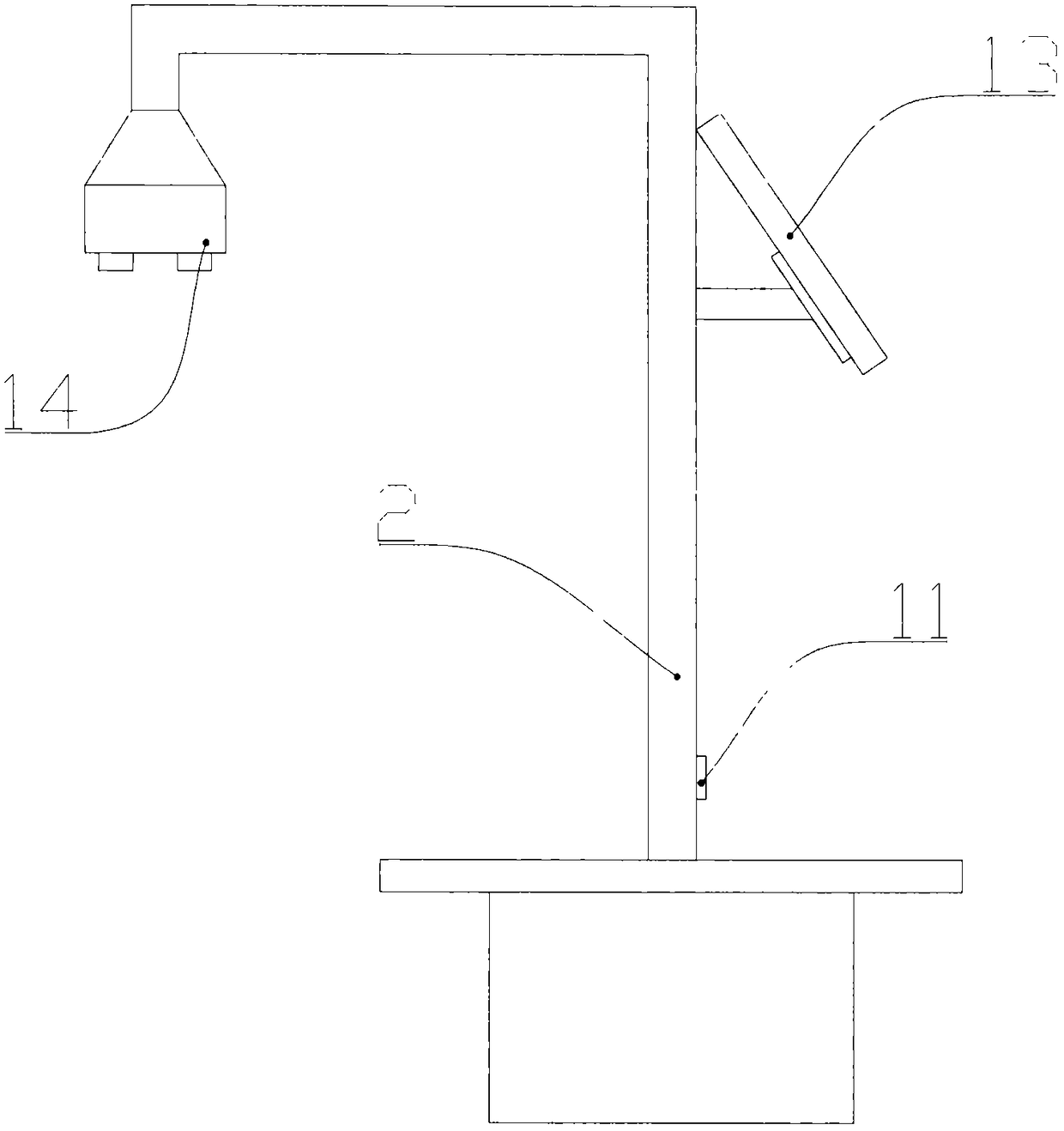
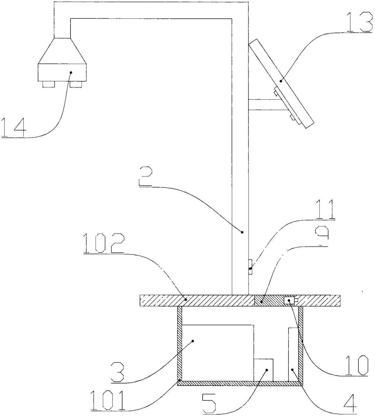
[0031] like Figure 1-5 As shown, a real-time monitoring data transmission device for snow depth changes includes a housing 1 and a pole 2. The housing 1 includes a storage box 101 buried in the ground and a cover plate 102 arranged on the upper end of the storage box 101. The box 101 and the cover plate 102 form a closed accommodation space, and the storage box 101 is provided with a high-energy lithium battery 3 that provides electric...


PUM


Abstract

The invention discloses a real-time monitoring data transmission device for snow depth change. The device comprises a shell and an upright rod, the shell comprises a storage box and a cover plate, thestorage box is internally provided with a high power lithium battery, a microprocessor and an electric quantity monitoring module, and a GPS module, a Bluetooth module and a LoRa radio-frequency transceiving module are electrically connected to the microprocessor; a door plate is connected to the cover plate, and an electromagnetic lock is arranged at the end of the door plate; a fingerprint unlocking device is arranged on the upright rod, a solar panel assembly is fixed to the middle of the upright rod, and the power output end of the solar panel assembly is connected with the high power lithium battery; a distance measuring sensor is arranged at the other end of the upright rod, a main control switch which is electrically connected with the microprocessor through a wire is electricallyconnected to the distance measuring sensor, and the microprocessor is electrically connected to the main control switch through a signal line. The real-time monitoring data transmission device has theadvantages that the device is intellectualized, saves energy, has long battery life, a good sealing effect, high corrosion resistance, and a long data transmission distance, and is convenient to manage.

Description

technical field [0001] The invention belongs to the technical field of snow monitoring equipment, and in particular relates to a data transmission device for real-time monitoring of snow depth changes. Background technique [0002] In northern my country, snowfall is relatively frequent in winter, and some areas even experience long-term continuous snowfall, especially in pastoral areas in northern my country, where long-term continuous snowfall or blizzard depth of snow is very deep, which is harmful to livestock breeding. serious threat. [0003] In order to make timely and effective snow disaster emergency response measures, it is necessary to monitor snowfall in a fixed area, and to know the snowfall speed in the monitored area in real time through the monitoring device on the change of snow depth in the monitored area. Once there is a regional blizzard or In the event of heavy snowfall or rapid snowfall, relevant personnel of government departments can do emergency resc...

Claims


Application Information

Patent Timeline
Patent Type & Authority Applications(China)
IPC IPC(8): G01B17/02G06F21/32G08C17/02
CPCG01B17/02G06F21/32G06F2221/2133G08C17/02
Inventor 都伟冰王双亭李长春王涵魏峰远王春阳何宽
Owner HENAN POLYTECHNIC UNIV
Why Eureka
Try Eureka