Safety injection and containment spray mutual standby pipeline system of nuclear power station and verification method on basis of safety injection and containment spray mutual standby pipeline system

A verification method and technology for nuclear power plants, which are applied to the pipeline system of nuclear power plants where safety injection and injection safety and injection are mutually backup and the field of verification, can solve the problems of flow-induced vibration, high risk of operator exposure to radiation, and low reliability of the equipment itself. Enhance reliability, improve economic efficiency, and optimize the effect of debugging critical paths

Inactive Publication Date: 2018-10-16
中广核工程有限公司 +1
View PDF5 Cites 2 Cited by
  • Summary
  • Abstract
  • Description
  • Claims
  • Application Information

AI Technical Summary

Problems solved by technology

[0005] The present invention aims at the fact that the H4 pipeline in the prior art, which is used as a backup for each other, basically does not have the function of emergency mutual backup. The operation leads to low reliability of the equipment body and the high flow rate in the H4 pipeline, which may induce the risk of flow-induced vibration. An H4 pipeline is provided to ensure safe injection / containment spraying can quickly realize backup, and can realize safety Casing spray pump fast standby safety injection pump for cold section injection, which enhances the reliability during accident operation, ensures the safe and reliable operation of nuclear power units, and improves the economic benefits of nuclear power plants

Method used


Image

  • Safety injection and containment spray mutual standby pipeline system of nuclear power station and verification method on basis of safety injection and containment spray mutual standby pipeline system
  • Safety injection and containment spray mutual standby pipeline system of nuclear power station and verification method on basis of safety injection and containment spray mutual standby pipeline system
  • Safety injection and containment spray mutual standby pipeline system of nuclear power station and verification method on basis of safety injection and containment spray mutual standby pipeline system

Examples


Embodiment 1

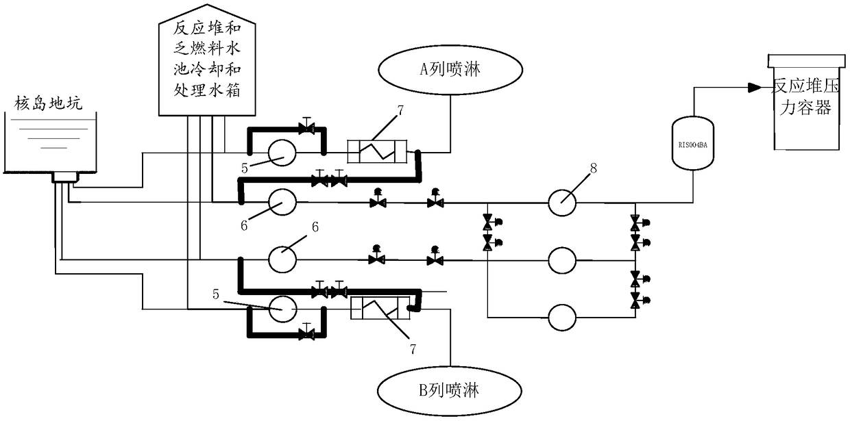
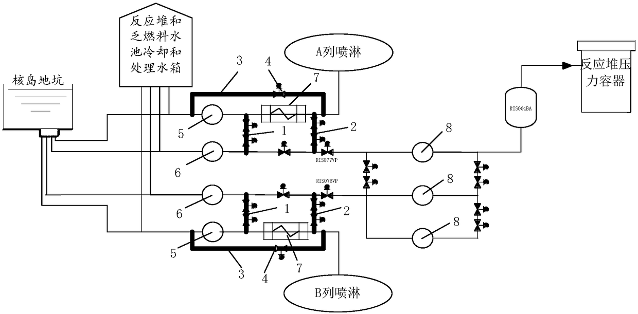
[0039] Such as figure 2 As shown, Embodiment 1 of the present invention provides a pipeline system in which safety injection and safety injection are mutually backup, including at least one set of H4 pipelines connected between the safety injection system and the containment spray system. In this embodiment, Including two sets of H4 pipelines respectively connected to the same safety injection system of columns A and B and the containment spraying system, so that the safety injection pumps and containment spraying pumps of columns A and B can be used during accident mitigation Each column of safety injection system includes nuclear island pit, low-pressure safety injection pump 6, high-pressure safety injection pump 8 and reactor pressure vessel which are sequentially connected by pipelines, and each column of safety spray system includes sequentially connected by pipelines Reactor and spent fuel pool cooling and processing water tank, containment spray pump 5 and containment...

Embodiment 2

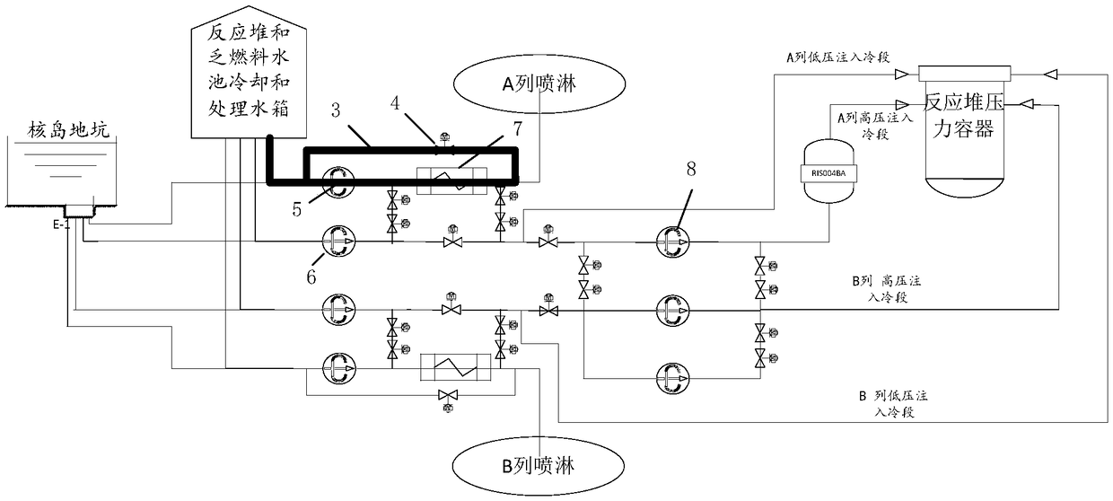
[0042] Embodiment 2 of the present invention also provides a verification method, which uses multiple test conditions to verify that the safety injection and safety spray are mutually standby pipeline systems, and the multiple test conditions include: containment spray flow operating conditions, Containment spray pump standby low-pressure safety injection pump working condition, low-pressure safety injection pump standby containment spray pump spray working condition, two-row low-pressure safety injection pump using containment spray heat exchanger cold section injection working condition.

[0043] Specifically, the containment spray flow operating conditions include the containment spray flow operating conditions of columns A and B; the containment spray pump standby low-pressure safety injection pump operating conditions include the injection condition of the cold section, the increase One high-pressure safety injection pump cold section injection working condition of pressur...


PUM


Abstract

The invention discloses a safety injection and containment spray mutual standby pipeline system of a nuclear power station. The safety injection and containment spray mutual standby pipeline system comprises at least one group of H4 pipelines. The H4 pipelines are arranged between safety injection systems and containment spray systems in a connected manner, each group of H4 pipelines comprises a first connecting pipeline, a second connecting pipeline and a containment spray pump backflow pipeline; one end of each first connecting pipeline is arranged on an outlet pipeline of a containment spray pump in a communicated manner, and the other end of each first connecting pipeline is arranged on an outlet pipeline of a low-pressure safety injection pump in a communicated manner; one end of eachsecond connecting pipeline is arranged on an outlet pipeline of a containment spray heat exchanger in a communicated manner, each containment spray heat exchanger is positioned on downstream of the corresponding containment spray pump, the other end of each second connecting pipeline is arranged on an outlet downstream pipeline of the corresponding low-pressure safety injection pump in a communicated manner, and a joint of each second connecting pipeline and the downstream pipeline of the corresponding low-pressure safety injection pump is positioned on upstream of a high-pressure safety injection joint; one end of each containment spray pump backflow pipeline is arranged on an outlet downstream pipeline of the corresponding containment spray heat exchanger in a communicated manner, and the other end of each containment spray pump backflow pipeline is arranged on an inlet pipeline of the corresponding containment spray pump in a communicated manner. The invention further provides a test method on the basis of the safety injection and containment spray mutual standby pipeline system of the nuclear power station.

Description

technical field [0001] The invention relates to the technical field of nuclear power plant operation, in particular to a pipeline system in which the safety injection and safety spraying of nuclear power plants serve as backups for each other and a verification method thereof. Background technique [0002] In the long-term period after the coolant loss accident (15 days after the accident), when two low-pressure safety injection pumps or two safety injection pumps fail, the safety injection pump and the safety injection pump can be used as backups for each other, and the direction of flow can be maintained. Core injection function. The corresponding working conditions and operating procedures are called "H4 working conditions" and "H4 regulations" respectively. [0003] In the prior art, the H4 pipeline consists of two pipelines in each safety series, such as figure 1 As shown, one of them is connected from the outlet of the safety injection heat exchanger to the inlet of ...

Claims


Application Information

Patent Timeline
Patent Type & Authority Applications(China)
IPC IPC(8): G21C15/18
CPCG21C15/182Y02E30/30
Inventor 闫明晶朱峰惠珑伟章松林周创彬李盛杰彭跃孔斌王江洪赵鑫翟巴菁朱增培王峰廖彤彤白旋王志明韩立杰詹华斌姚孟琦赵晓鹏
Owner 中广核工程有限公司
Why Eureka
Try Eureka