A power supply device and power supply method

A technology of power supply device and power supply mode, which is applied in the field of power supply, can solve problems such as unsuitable primary-side feedback topology, output current over-pulse, complex circuit design, etc., achieve outstanding energy-saving effects, meet power consumption needs, and low cost.

Active Publication Date: 2020-11-27
TRIDONIC
View PDF5 Cites 0 Cited by
  • Summary
  • Abstract
  • Description
  • Claims
  • Application Information

AI Technical Summary

Problems solved by technology

However, in order to realize the specific functions of this kind of power supply device, in addition to providing an additional secondary-side power supply circuit, it is also necessary to work hard to solve the timing problems of the DC conversion circuit and the secondary-side supply current, as well as technical difficulties such as output current over-pulse.
[0003] In addition, the circuit design of this power supply device is complex and expensive, and it is not suitable for the topology of the primary side feedback

Method used


Image

  • A power supply device and power supply method
  • A power supply device and power supply method
  • A power supply device and power supply method

Examples


Embodiment 1

[0046] This embodiment discloses the first power supply device, Figure 4 Shows the circuit diagram of the first power supply device of the present invention, as Figure 4 As shown, in the first power supply device, the switch sub-circuit 401 includes a first diode D63, a first resistor R66, a second resistor R68, a third resistor R72, a fourth resistor R63, a fifth resistor R64, The sixth resistor R67, the first triode Q61, the first optocoupler U21; the power supply mode setting sub-circuit includes the first MOS transistor M22, the eighth resistor R26 and the ninth resistor R29 connected in parallel, the tenth resistor R32, The eleventh resistor R33, and the first capacitor C27 connected in parallel at both ends of the eleventh resistor R33; wherein:

[0047] One end of the first resistor R66 is connected to the positive output terminal LED+, the other end of the first resistor R66 is connected between the positive pole of the first diode D63 and the second negative output...

Embodiment 2

[0055] This embodiment provides a second lighting device, Figure 5 Shows the circuit diagram of the second power supply device of the present invention, as Figure 5 As shown, in the second power supply device, the switch sub-circuit 401 includes a first diode D63, a first resistor R66, a second resistor R68, a third resistor R72, a fourth resistor R63, a fifth resistor R64, The sixth resistor R67, the first triode Q61, the first optocoupler U21; the power supply mode setting sub-circuit 402 includes the first MOS transistor M22, the eighth resistor R26, the ninth resistor R29, and the tenth resistor R32 connected in parallel , the eleventh resistor R33, and the first capacitor C27 connected in parallel at both ends of the eleventh resistor R33; wherein:

[0056] One end of the first resistor R66 is connected to the positive output terminal LED+, the other end of the first resistor R66 is connected between the positive pole of the first diode D63 and the second negative outp...

Embodiment 3

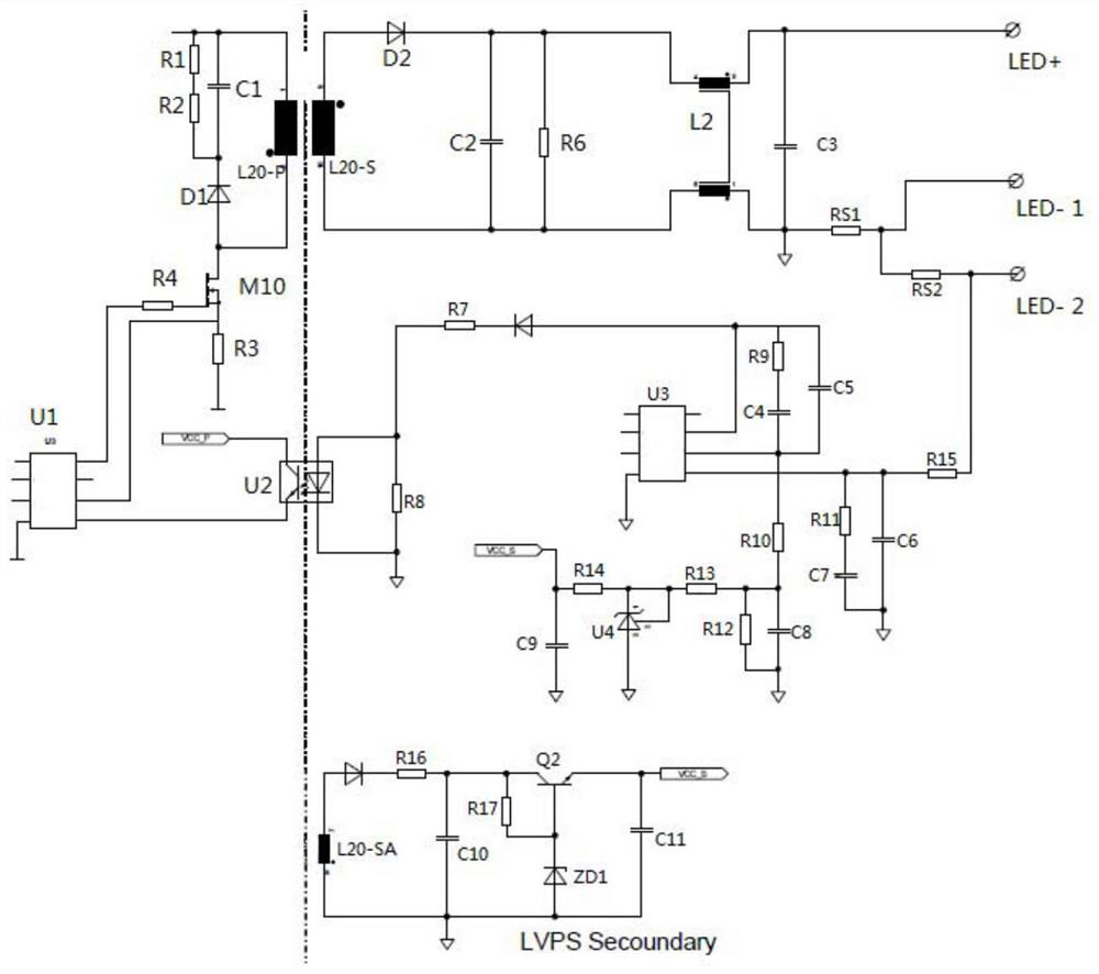
[0066] This embodiment discloses a third power supply device, which further includes a secondary side power supply circuit 600 connected to the power supply mode selection circuit 400 and used to supply power to the power supply mode selection circuit 400 alone.

[0067] Image 6 Shows the circuit diagram of the third power supply device of the present invention, as Image 6 As shown, in the third power supply device, the switch sub-circuit 401 includes a first resistor R66, a second resistor R68, a third resistor R72, a fourth resistor R63, a sixth resistor R67, a second MOS transistor M61, a A transistor Q61, a PNP type second transistor Q62, a twelfth resistor R73, a thirteenth resistor R74 and a fourteenth resistor R75, and a first optocoupler U21; the power supply mode setting subcircuit 402 includes The first MOS transistor M22, the eighth resistor R26 and the ninth resistor R29 connected in parallel, the tenth resistor R32, the eleventh resistor R33, and the first capa...


PUM


Abstract

A power supply device and a power supply method. Wherein, the power supply device includes a power supply (100), a DC conversion circuit (200), a current output port (800), a power supply mode selection circuit (400) and a control circuit (500). The power supply mode selection circuit (400) is used for generating a first power supply mode setting signal or a second power supply mode setting signal according to the connection mode of the load (700) and the current output port (800). The control circuit (500) is configured to control the DC conversion circuit (200) to enter the first power supply mode when receiving the first power supply mode setting signal, and make it perform DC conversion according to the first operating frequency to output the first drive current, or when receiving the second power supply mode setting signal, control the DC conversion circuit (200) to enter the second power supply mode, and make it perform DC conversion according to the second operating frequency, so as to output the second drive current. The power supply device of the invention has the advantages of simple circuit structure and low cost.

Description

technical field [0001] The present invention relates to the field of power supply technology, and more specifically, relates to a power supply device and a power supply method capable of providing multiple output current specifications. Background technique [0002] The power supply devices on the market generally have the disadvantages of complicated circuit design and high cost. For example, the description of the present invention is attached figure 1 Disclosed is a common power supply device on the market that can provide two kinds of output current specifications. Please refer to the attached figure 1 , when the positive input terminal of the load is connected to the positive input terminal of the power supply, and the negative input terminal of the load is connected to the first negative output terminal of the power supply, the power supply device can output the first preset current to the load, and when the positive input terminal of the load When the terminal is c...

Claims


Application Information

Patent Timeline
Patent Type & Authority Patents(China)
IPC IPC(8): H02M3/156H05B45/37H05B44/00
CPCH02M3/156H05B45/382H05B45/3725H02M3/1566H02M3/33523H02M3/33561H02M3/33576Y02B70/10H02M1/0025H02M1/0032H02M1/009
Inventor 毛秋翔陈志文柯其涛钟国基
Owner TRIDONIC
Why Eureka
Try Eureka