Jianbing making machine
A technology of pancake machine and machine head, which is applied in the direction of baking pancakes, frying pan, baking, etc. It can solve the problem of uneven delivery of batter and slurry, and achieve the effect of increasing eating pleasure
- Summary
- Abstract
- Description
- Claims
- Application Information
AI Technical Summary
Problems solved by technology
Method used
Image
Examples
Embodiment 1
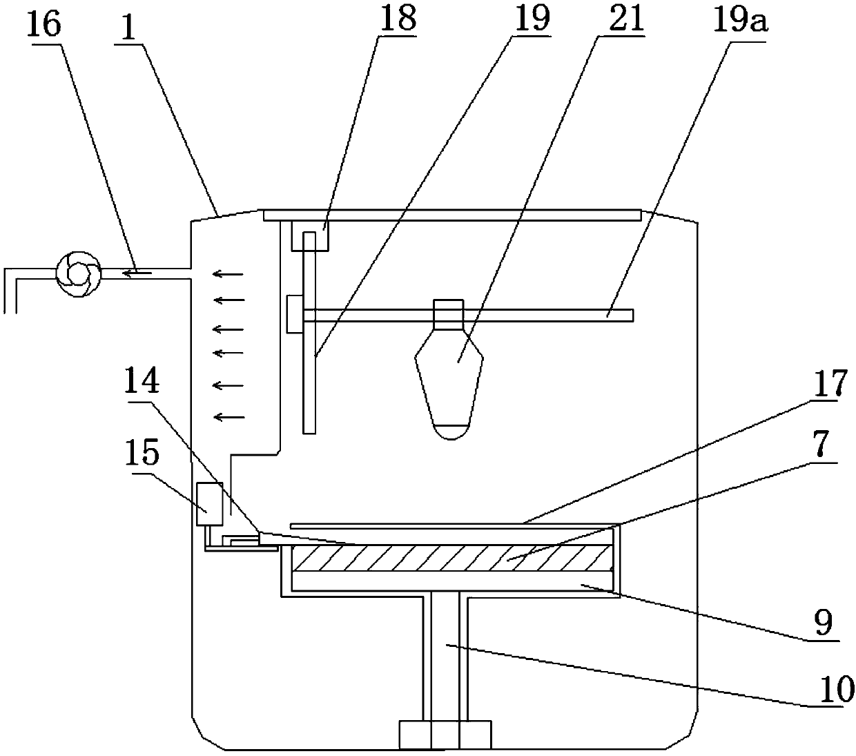
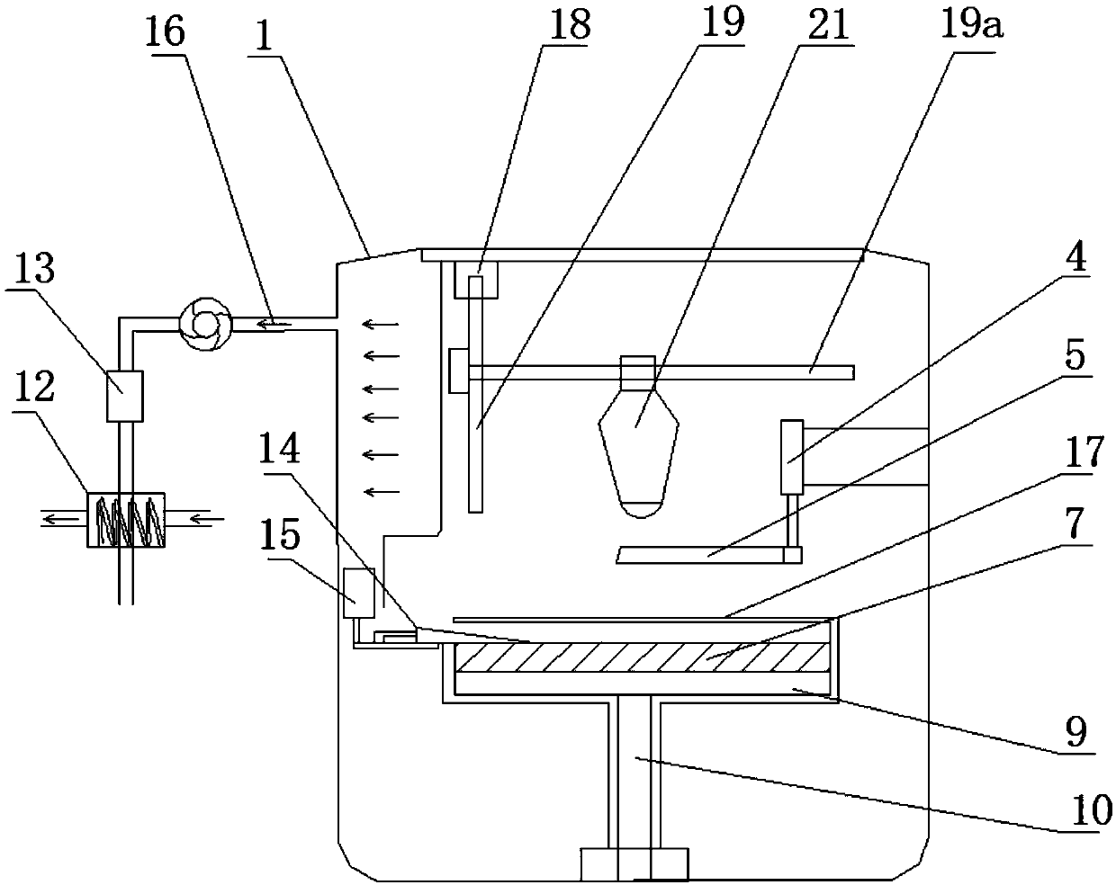
[0049] to combine Figure 1 to Figure 2As shown, the present embodiment provides a pancake machine, which includes: 3D printing blanking device; the 3D printing blanking device includes: blanking machine head, X-axis moving mechanism 19A, Y-axis moving mechanism 19, Z-axis moving mechanism Mechanism 18 and controller; the feeding machine head is used to put batter slurry; the X-axis moving mechanism 19A is connected with the feeding machine head to drive the feeding machine head to move along the X-axis direction; the Y-axis moving Mechanism 19 is connected with the X-axis moving mechanism 19A, and is used to drive the X-axis moving mechanism 19A and the blanking machine head to move together along the Y-axis direction; the Z-axis moving mechanism 18 is connected with the Y-axis moving mechanism 19. To drive the Y-axis moving mechanism 19, the X-axis moving mechanism 19A and the blanking machine head to move along the Z-axis direction, the controller moves with the X-axis movi...
Embodiment 2
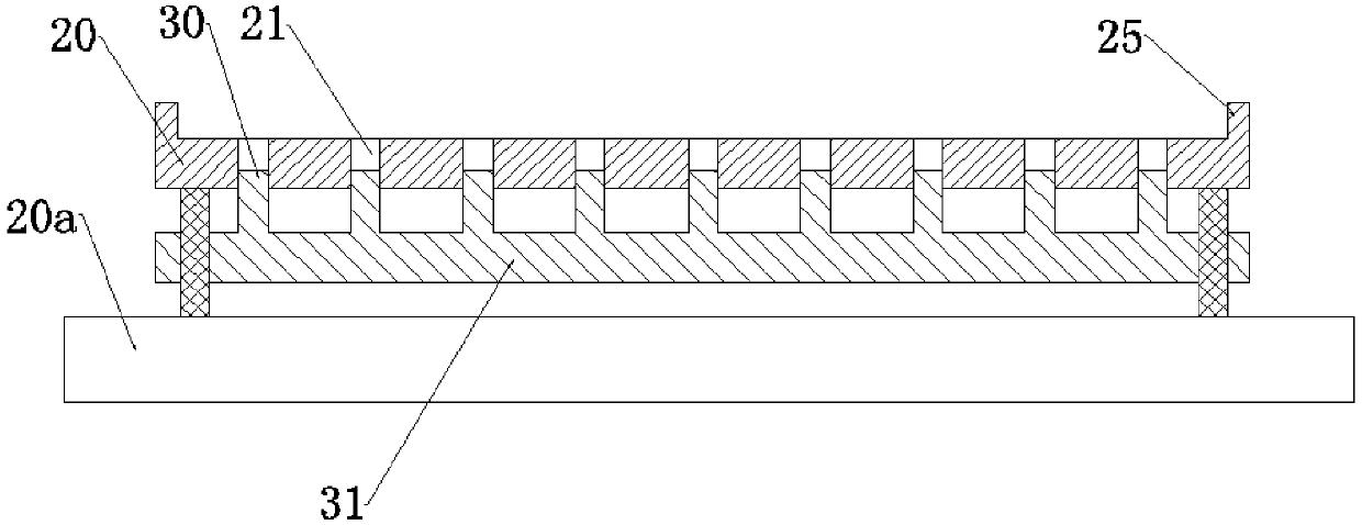
[0072] like Figure 3-5 As shown, the structural design of the griddle 20 in a pancake machine provided by this embodiment is different, and also includes: a push rod 30 and a jacking actuator;
[0073] A plurality of first shaft holes 21 are arranged on the plate 20;
[0074] The push rod 30 is telescopically and slidably arranged on the first shaft hole 21;
[0075] The jack-up actuator is used to drive the push rod 30 to move up and down along the first shaft hole 21, so that the top of the push rod 30 protrudes from the upper edge of the first shaft hole 21 or retreats into the first shaft hole 21; the top of the push rod 30 extends When going out of the first shaft hole 21, the top of the push rod 30 protrudes from the upper surface of the griddle 20, forcing the cake body 60 above the griddle 20 to separate from the griddle 20.
[0076] This embodiment also includes a base 20a and a first bracket 31; the grid plate 20 and the base 20a are spaced apart; the first bracke...
Embodiment 3
[0085] The structure of this embodiment is the same as that of Embodiment 2, the difference is that:
[0086] like Figure 7 As shown, when the top of the push rod 30 protrudes from the upper edge of the first shaft hole 21, the push rod 30 includes a protruding portion 30a protruding from the first shaft hole 21; an air blowing hole 33 is provided on the outer surface of the protruding portion 30a , The ejector rod 30 is provided with a gas channel 34 inside, and the air blowing hole 33 is connected to the pressure gas source through the gas channel 34 and the gas pipeline. The gas pipeline is provided with a control switch and a controller for controlling gas on-off. Control switches and controllers are prior art and will not be repeated here. Wherein the pressure gas source preferably adopts a small air pump.
[0087] After the ejector pin 30 is lifted, while the protruding part 30a lifts the cake body, the pressure gas source blows air to the bottom of the cake body thr...
PUM
 Abstract
Description
Claims
Application Information
 - R&D
- Intellectual Property
- Life Sciences
- Materials
- Tech Scout
- Unparalleled Data Quality
- Higher Quality Content
- 60% Fewer Hallucinations
Browse by: Latest US Patents, China's latest patents, Technical Efficacy Thesaurus, Application Domain, Technology Topic, Popular Technical Reports.
© 2025 PatSnap. All rights reserved.Legal|Privacy policy|Modern Slavery Act Transparency Statement|Sitemap|About US| Contact US: help@patsnap.com


