
Working channel system of diskoscope

A working channel and intervertebral disc technology, applied in the field of intervertebral disc endoscope working channel system, can solve the problems of limiting the promotion and development of minimally invasive spinal surgery, limiting surgical indications, and small operable range, breaking the monopoly of foreign technology and increasing the number of surgeries. The scope of operation, the effect of reducing procurement costs

Pending Publication Date: 2018-10-19
黎庆初
View PDF18 Cites 0 Cited by
  • Summary
  • Abstract
  • Description
  • Claims
  • Application Information

AI Technical Summary

Problems solved by technology

[0003] At present, the clinical effect of the discoscopy working channel system in clinical application has been widely recognized, but the field of view of these discoscopy working channels is limited, and the operable range is small, which limits its surgical indications
Moreover, at present, the research and development of the operating system that my country's minimally invasive spinal surgery must rely on is monopolized by foreign countries and developed by different companies. They are incompatible with each other, have extremely poor versatility, and are expensive. The price of a minimally invasive operating system is generally around 1 million yuan. Hospitals often need to purchase 3-4 or more operating systems to carry out some mainstream minimally invasive spinal surgery, which largely limits the promotion of minimally invasive spinal surgery And development

Method used


Image

  • Working channel system of diskoscope
  • Working channel system of diskoscope
  • Working channel system of diskoscope

Examples


Embodiment 1

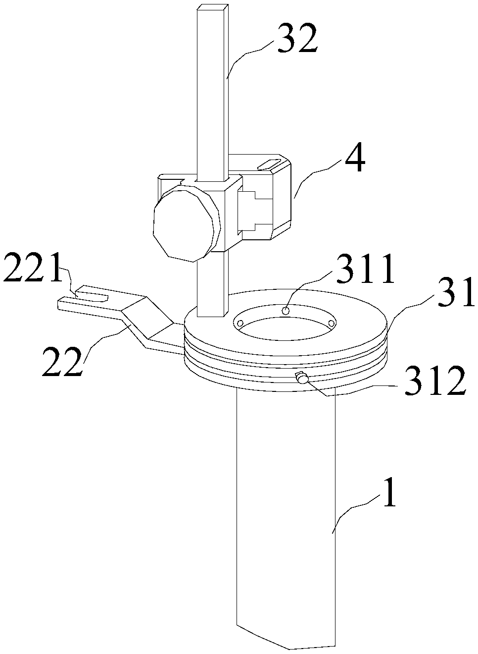
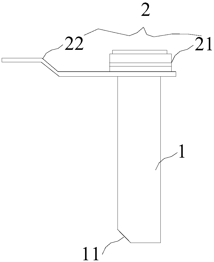
[0032] Such as Figure 1~8 , The intervertebral disc mirror working channel system of this embodiment includes a working channel tube 1, a connecting rod 2, a connecting ring device 3, and an intervertebral disc mirror fixing device 4. An oblique cut 11 is provided at the port of one end of the working channel tube 1. The connecting rod 2 is detachably fixed to the other end of the working channel tube 1, and includes a first connecting portion 21 and a handle portion 22. The first connecting portion 21 is connected to the handle portion 22. In this embodiment, the first connecting portion 21 is a ring. The handle part 22 is provided with a system fixing part 221 through which the entire disc mirror working channel system can be connected with other external fixing devices.

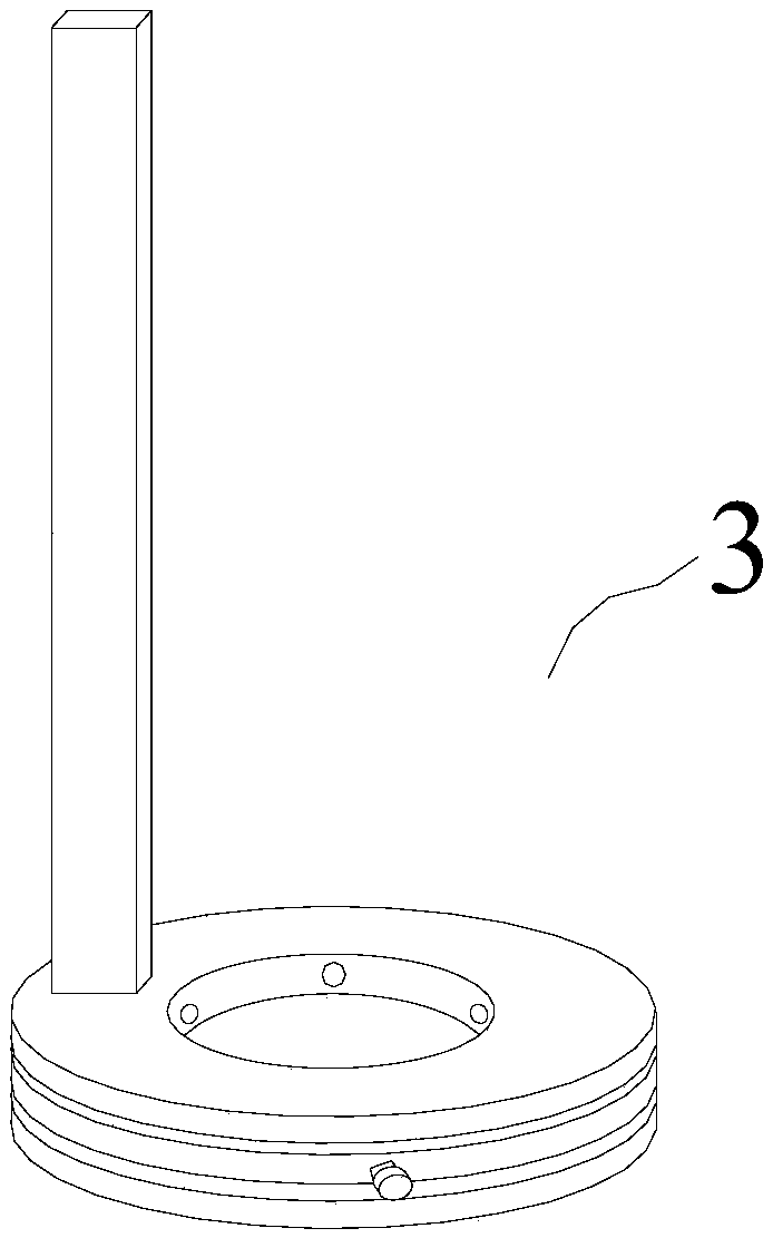
[0033] The connecting ring device 3 includes a connecting ring 31 and a connecting column 32, and the connecting column 32 is vertically fixed to the connecting ring 31. The connecting ring 31 is provided ...


PUM


Abstract

The invention relates to a working channel system of a diskoscope, which comprises a working channel pipe, a connecting rod, a connecting ring device and a diskoscope fixing device, wherein the connecting rod is fixed at one end of the working channel pipe; the connecting ring device comprises a connecting ring and a connecting column; the connecting column is vertically fixed on the connecting ring; the diskoscope fixing device comprises a first fixing part and a second fixing part, wherein the first fixing part can be vertically and slidably fixed on the connecting column, and the second fixing part can be horizontally and slidably fixed on the first fixing part, the diskoscope is fixed on the second fixing part. By adopting the working channel system of the diskoscope, the diskoscope can be moved in three directions of up and down, left and right and front and back, so that the distance between the diskoscope and the surgical site can be adjusted conveniently during a surgery, and the operation range is increased; and the field of view in the channel is enlarged through a simple structure.

Description

Technical field [0001] The invention relates to the field of medical equipment, in particular to an intervertebral disc mirror working channel system. Background technique [0002] Since the 1980s, minimally invasive spinal surgery technology has achieved rapid development, and has been widely used and recognized in the industry, bringing good news to millions of patients with spinal diseases worldwide. This technology is about to lead the future development of spinal surgery. The trend. The disc mirror working channel system is an indispensable tool for minimally invasive spine surgery technology. It can provide an effective operating space and ensure the smooth completion of the operation in a relatively narrow space, thereby minimizing damage to the surrounding tissues. [0003] At present, the clinical effect of the working channel system of intervertebral disc mirrors in clinical application has been widely recognized. However, the working channel of these disc mirrors has a ...

Claims


Application Information

Patent Timeline
Patent Type & Authority Applications(China)
IPC IPC(8): A61B17/00
CPCA61B17/00234A61B2017/00261A61B2017/0034
Inventor 黎庆初刘则征杨洋陈志旭
Owner 黎庆初
Learn More