Throat area adjustable static momentum-enhanced ejector

A throat area and injector technology, applied in the direction of injection devices, liquid injection devices, etc., can solve the problems of small adjustment range, loss of turbulent kinetic energy in the central flow field, fixed structural size, etc., to improve ejection performance and enhance momentum exchange , the effect of good application prospects

Active Publication Date: 2018-10-19
艾肯(江苏)工业技术有限公司
View PDF6 Cites 6 Cited by
  • Summary
  • Abstract
  • Description
  • Claims
  • Application Information

AI Technical Summary

Problems solved by technology

However, traditional injectors have the problem of fixed and non-adjustable structural dimensions, and only have a single optimal working condition. Faced with fluctuations in on-site working conditions, they do not have operational flexibility
[0003] The current injector patent "a self-excited back-spin jet booster" (application number: 201710042657.8) adds an adjusting cone whose cross-sectional area varies with the axial direction to the driving nozzle, and changes the driving force by changing the axial position of the adjusting cone. The nozzle flow area is adjusted to adjust the throat area, and there is turbulent kinetic energy loss in the central flow field
However, "A injector with adjustable inner wall structure" (authorized announcement number: 105570202B) adjusts the relative axial distance between the mixing chamber and the driving nozzle by changing the shape of the suction chamber, and the adjustment range is small
"Assembled Injector with Adjustable Throat-Nozzle Distance" (Application No.: 201720370477.8) adjusts the position of the nozzle through threads, only the axial position can be adjusted, and it does not have the ability to adjust the optimal working conditions under different working conditions

Method used


Image

  • Throat area adjustable static momentum-enhanced ejector
  • Throat area adjustable static momentum-enhanced ejector
  • Throat area adjustable static momentum-enhanced ejector

Examples


Embodiment Construction

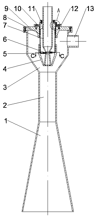
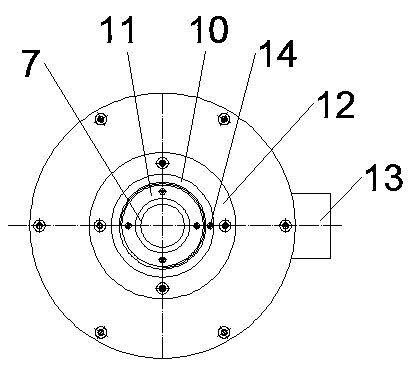
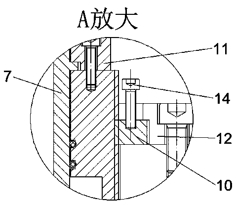
[0032] figure 1 , 2 , 3, 4, 5, 6 show the structural diagram of a static momentum enhanced injector with adjustable throat area. The static momentum enhanced injector with adjustable throat area includes a zoom-shaped working outer cavity and a main flow nozzle adjustment mechanism. The zoom-shaped working outer chamber includes the upper end surface 9 of the injector, the suction chamber 3 , the mixing chamber 2 , the expansion section 1 and the secondary inflow port 13 . The mainstream nozzle adjustment mechanism includes an adjustable base 4 , a rigid metal insert 5 , a driving nozzle base 7 and an axial adjustment base 8 . The axial adjustment base 8 is fixed at the center of the upper end surface 9 of the injector and extends into the suction chamber 3, the adjustable base 4 is screwed to the end of the axial adjustment base 8, the nozzle gland 11 drives the nozzle base 7 It is arranged in the axial adjustment base 8 in an axially limited and circumferentially rotating...


PUM


Abstract

The invention provides a throat area adjustable static momentum-enhanced ejector and belongs to the technical field of fluid jet pressurization. The ejector is subjected to operation optimization andcan realize adjustment of the large-scale working condition through an adjusting mechanism. The throat area corresponds to the rotating angle. The optimum condition under different parameters can be rapidly located through stepless adjustment of the throat area and the axial position of a spray nozzle. A rigid metal insertion sheet is fixedly constrained between a driving spray nozzle through holeand an adjustable base groove. The throat area adjustable static momentum-enhanced ejector is concise, firm, high in shock resistance and more suitable for fluid flowing. A static momentum-enhanced structure is added to a driving spray nozzle outlet. Generated disturbance can fully develop to induce fluid to conduct circumferential and radial momentum exchange, momentum exchange of driving fluidand driven fluid is enhanced, the length of a mixing chamber is shortened, and the ejecting performance is improved. Different types of rigid metal insertion sheets and static rotational flow structures can be selected to adapt to different requirements. An operator just needs to exchange different rigid metal insertion sheets and adjustable bases. The throat area adjustable static momentum-enhanced ejector is convenient to adjust.

Description

technical field [0001] The invention relates to a static momentum enhanced injector with adjustable throat area, which belongs to the technical field of fluid jet boosting. Background technique [0002] The injector injects low-pressure fluid by using the suction of the driving fluid, and plays the role of pressurized injection. The injector has the advantages of simple structure, convenient disassembly and assembly, and wide applicability, and is widely used in fluid pressurization and ejection. However, the traditional injector has the problem of fixed and non-adjustable structural size, and only has a single optimal working condition. It does not have operational flexibility in the face of fluctuations in on-site working conditions. [0003] The current injector patent "a self-excited back-spin jet booster" (application number: 201710042657.8) adds an adjusting cone whose cross-sectional area varies with the axial direction to the driving nozzle, and changes the driving ...

Claims


Application Information

Patent Timeline
Patent Type & Authority Applications(China)
IPC IPC(8): B05B7/04B05B7/12
CPCB05B7/04B05B7/12
Inventor 代玉强姚轶智胡大鹏张博文武锦涛张大为李陌晗陆朝洋
Owner 艾肯(江苏)工业技术有限公司
Why Eureka
Try Eureka