Stamping conveying equipment

A technology for conveying equipment and conveyor belts, applied in the field of stamping equipment, to achieve the effects of high work efficiency, simple production and low cost of use

Inactive Publication Date: 2018-10-19
广西晨天金属制品有限公司
View PDF0 Cites 0 Cited by
  • Summary
  • Abstract
  • Description
  • Claims
  • Application Information

AI Technical Summary

Problems solved by technology

[0003] The invention provides a stamping conveying equipment used to solve the problem of automatic feeding equipment instead of manual feeding in the stamping environment, and achieve the purpose of improving production efficiency, saving labor consumption, energy saving and environmental protection, and ensuring production safety

Method used


Image

  • Stamping conveying equipment
  • Stamping conveying equipment
  • Stamping conveying equipment

Examples


Embodiment Construction

[0018] specific implementation plan

[0019] The present invention is described in detail below in conjunction with accompanying drawing:

[0020] In the description of the present invention, it should be noted that the orientations or positional relationships indicated by the terms "X axis", "Y axis", "left side", "lower side" etc. are based on the orientations or positional relationships shown in the drawings , or the orientation or positional relationship that the product of the invention is usually placed in use is only for the convenience of describing the present invention and simplifying the description, rather than indicating or implying that the device or element referred to must have a specific orientation or be constructed in a specific orientation and operation, and therefore should not be construed as limiting the invention.

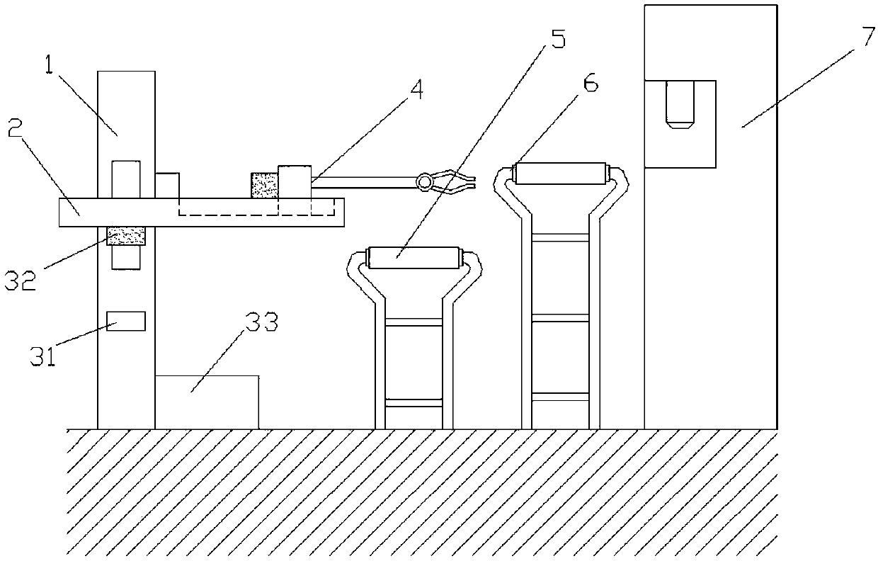
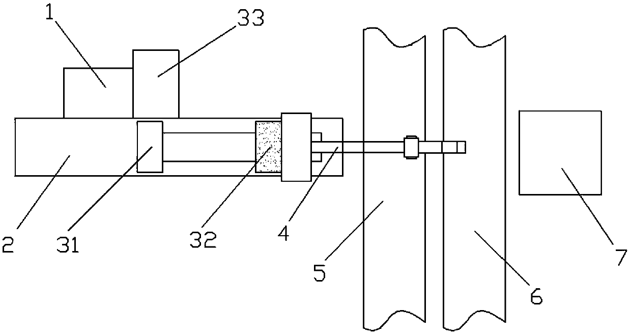
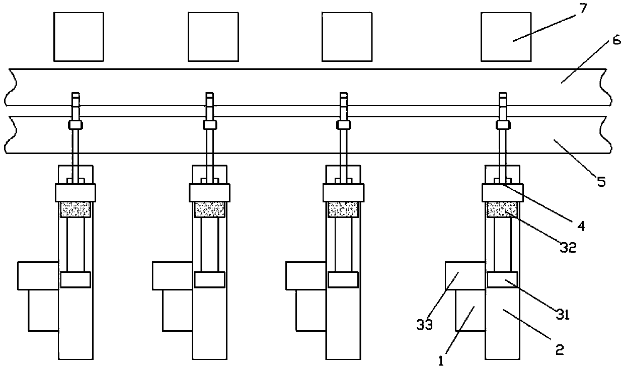
[0021] Such as figure 1 As shown, a stamping conveying equipment includes a Y-axis slide rail 1, an X-axis slide rail 2, a driving device...


PUM


Abstract

The invention discloses stamping conveying equipment. The stamping conveying equipment comprises a Y-axis sliding rail, an X-axis sliding rail, a driving device, a conveying mechanical arm, a finishedproduct conveying belt and a blank conveying belt; the X-axis sliding rail is arranged on the Y-axis sliding rail in a sliding mode, and the X-axis sliding rail can move on the Y-axis sliding rail through the driving action of the driving device; and the conveying mechanical arm is arranged on the X-axis sliding rail in a sliding mode and is driven by the driving device, the finished product conveying belt and the blank conveying belt are sequentially arranged in front of the X-axis sliding rail, and the mounting position of the finished product conveying belt is lower than that of the blankconveying belt. The equipment has the advantages that the sliding rails are adopted as conveying carriers, so that the conveying accuracy is higher, manufacturing and producing are simple, and the usecost is low; electromagnets are adopted as the driving power, so that the control is more convenient and more accurate, and the efficiency is higher; and the complete conveying equipment is provided,the processes from feeding of a blank to discharging of a finished product are all involved, and streamline operation is realized.

Description

technical field [0001] The invention relates to the technical field of stamping equipment, in particular to a stamping conveying equipment. Background technique [0002] my country's stamping technology develops rapidly, and the proportion of stamping production in mechanical production continues to rise. Stamping technology has entered a period of rapid development. At the same time, it is particularly important for the adjustment of production structure. Because the traditional manual feeding stamping production method has processing Efficiency, processing speed, transmission accuracy, production safety and other convenient issues, it is becoming more and more important to replace this traditional production method with an automatic feeding mechanism. At present, as far as the stamping production of general enterprises is concerned, due to the patent and technical limitations of the fully automatic production line, the purchase and maintenance prices are relatively expensiv...

Claims


Application Information

Patent Timeline
Patent Type & Authority Applications(China)
IPC IPC(8): B21D43/10B21D43/12B21D45/02
CPCB21D43/105B21D43/12B21D45/02
Inventor 朱天成
Owner 广西晨天金属制品有限公司
Why Eureka
Try Eureka