Industrial machining clamp

A fixture and industrial technology, applied in the field of industrial processing fixtures, can solve the problems of inability to meet special workpiece clamping requirements, poor guiding effect of bench vise, clamping position offset, etc., to improve the scope of application, avoid offset, meet Support the desired effect

Inactive Publication Date: 2018-10-19
惠州市豪美仕智能技术有限公司
View PDF18 Cites 1 Cited by
  • Summary
  • Abstract
  • Description
  • Claims
  • Application Information

AI Technical Summary

Problems solved by technology

[0005] The object of the present invention is to provide a kind of industrial processing fixture, to solve the deficiency that the existing bench vise that proposes in the above-mentioned background technology generally has a small clamping area, and cannot meet the clamping requirements of some special workpieces; The guiding effect of the bench vise is poor. After a period of use, the clamping position will shift, the clamping force will be uneven, and the problems and deficiencies that will affect the clamping effect

Method used


Image

  • Industrial machining clamp
  • Industrial machining clamp
  • Industrial machining clamp

Examples


Embodiment approach

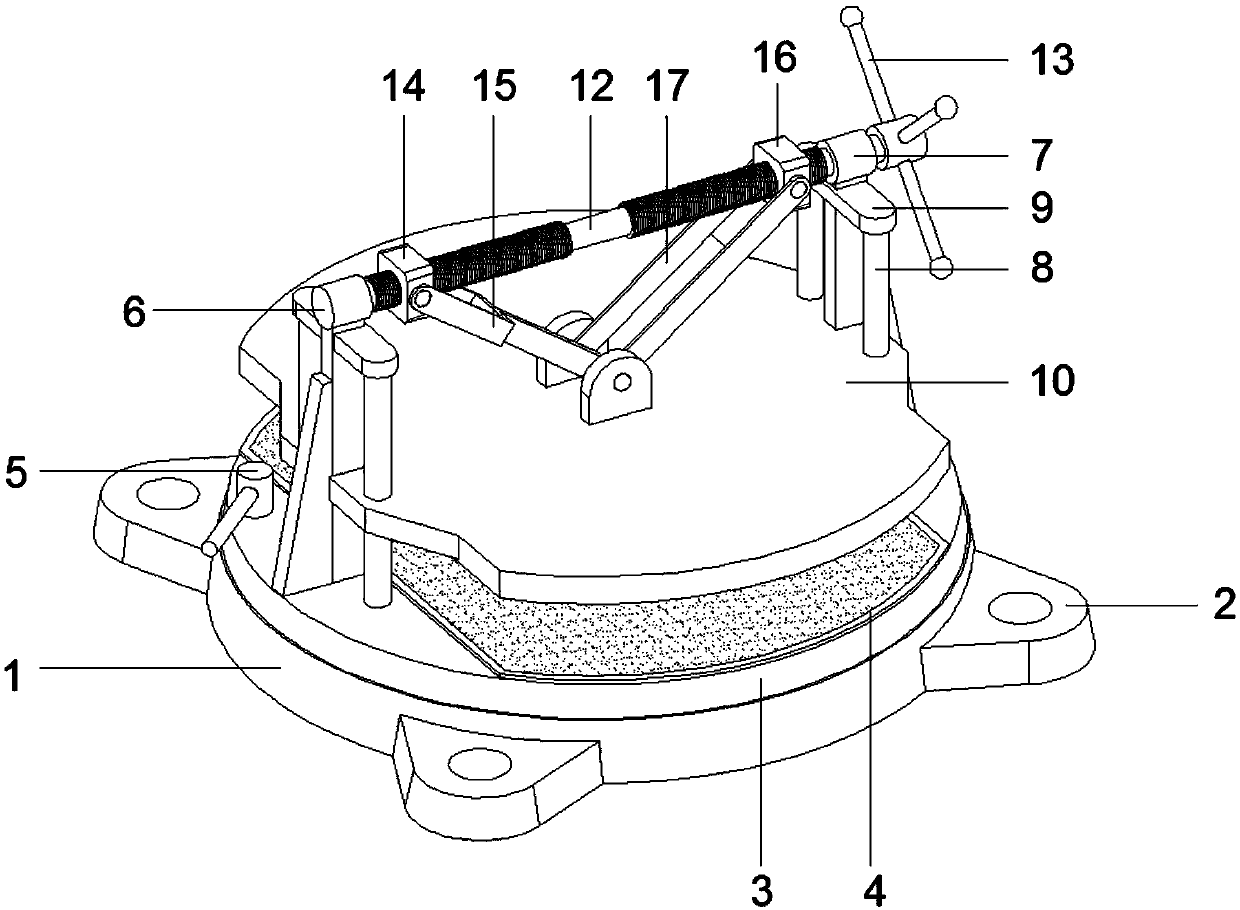
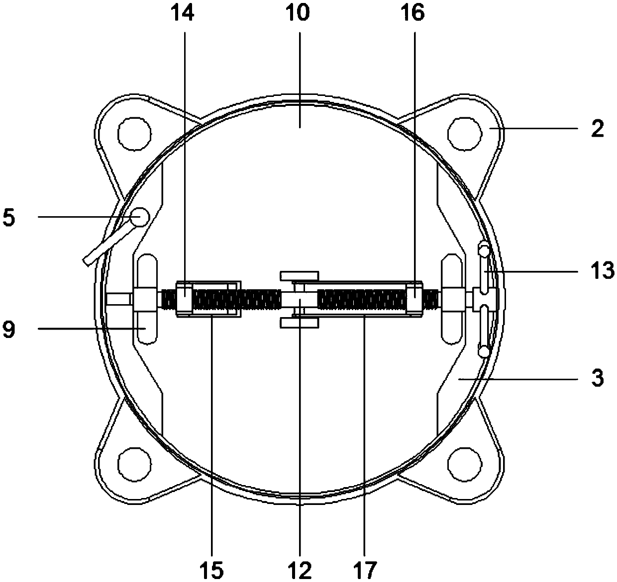
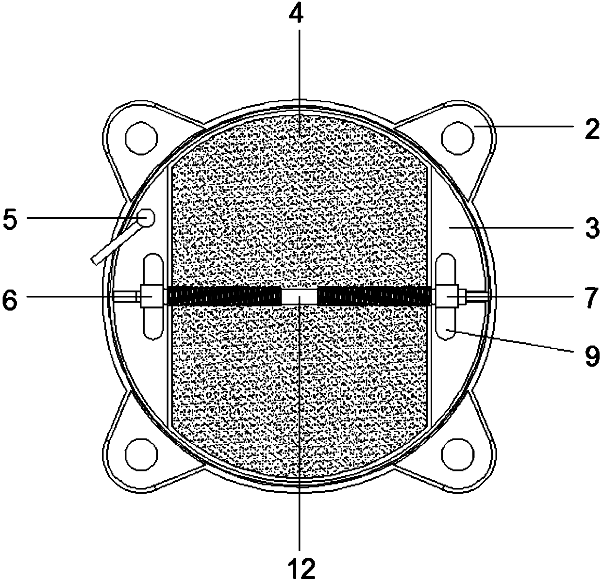
[0035]An industrial processing jig, the clamping area is large, the industrial processing jig has good guiding effect; it includes: chassis seat 1, mounting seat 2, base 3, fixed jaw 4, clamping handle 5, first support seat 6, second Two support bases 7, guide posts 8, guide post holders 9, splints 10, movable jaws 11, screw rods 12, rocking handles 13, first slides 14, first connecting rods 15, second slides 16, second Connecting rod 17; mounting seat 2 is arranged on both sides of chassis base 1, and mounting base 2 and chassis base 1 are integrated structure; base 3 is installed above chassis base 1, and the bottom of base 3 is embedded in chassis base 1 The inner side of the clamping handle 5 is embedded on the base 3; the first support base 6 is welded on one side of the top of the base 3, and the second support base 7 is welded on the other side of the top of the base 3; one end of the screw 12 Embedded and installed on the inside of the first support base 6, and the con...


PUM


Abstract

The invention provides an industrial machining clamp. The industrial machining clamp is large in clamping area and good in guiding effect. The industrial machining clamp comprises a bottom disc seat,mounting seats and a base. The mounting seats are arranged at the two sides of the bottom disc seat, and the mounting seats and the bottom disc seat are of an integrated structure. The base is mountedabove the bottom disc seat, and the bottom of the base is mounted at the inner side of the bottom disc seat in an embedded manner. A clamping handle is mounted on the base in an embedded manner. A first support seat is arranged at one side of the top end of the base in a welded manner, and a second support seat is arranged at the other side of the top end of the base in a welded manner. The industrial machining clamp is improved and has the advantages of being novel in structure, reasonable in design, large in clamping area, capable of meeting clamping requirements of different workpieces, wide in application scope, good in guiding effect, not prone to clamping position deviation, uniform in clamping force distribution, good in clamping effect and great in practicability; and thus, problems in the background art are effective solved, and defects in the background art are effectively overcome.

Description

technical field [0001] The invention relates to the technical field of fixtures, and more specifically, relates to an industrial processing fixture with a large clamping area and good guiding effect. Background technique [0002] Fixture refers to the device used to fix the processing object in the process of mechanical manufacturing so that it can occupy the correct position to accept construction or testing. Fixtures are a relatively common device in the field of industrial processing technology, and the current bench vise is an industrial processing A type of fixture that is more common and commonly used in the field. [0003] However, there are many problems and deficiencies in the actual use of existing bench vises, for example, the clamping area is small, and the existing bench vises generally have the deficiency of small clamping area, which cannot meet the clamping requirements of some special workpieces ; Another example is that the existing bench vise has a poor g...

Claims


Application Information

Patent Timeline
Patent Type & Authority Applications(China)
IPC IPC(8): B25B1/10B25B1/24
CPCB25B1/10B25B1/24B25B1/2405
Inventor 黎志瀛
Owner 惠州市豪美仕智能技术有限公司
Why Eureka
Try Eureka