
Robot joint arm and robot

A robot joint and encoder technology, applied in the field of robots, can solve the problems of large axial size of the motor and increase in the axial size of the robot joint arm, and achieve the effect of improving the functional density and reducing the axial size

Pending Publication Date: 2018-10-19
AUBO BEIJING ROBOTICS TECH CO LTD
View PDF12 Cites 2 Cited by
  • Summary
  • Abstract
  • Description
  • Claims
  • Application Information

AI Technical Summary

Problems solved by technology

[0003] In the prior art, the photoelectric encoder and the magnetic encoder are installed independently, which leads to a larger axial dimension of the motor, which in turn leads to an increase in the axial dimension of the entire robot joint arm

Method used


Image

  • Robot joint arm and robot
  • Robot joint arm and robot
  • Robot joint arm and robot

Examples


Embodiment Construction

[0045] In order to enable those skilled in the art to better understand the technical solutions of the present invention, the present invention will be further described in detail below in conjunction with the accompanying drawings and specific embodiments.

[0046] Words such as "first" and "second" mentioned herein are only used to describe two or more structures or components with the same or similar structures, and do not represent any special limitation on the order.

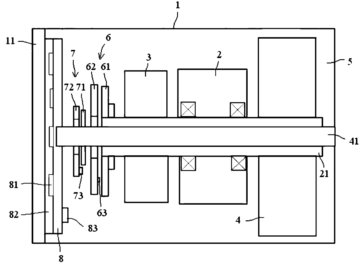
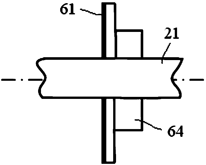
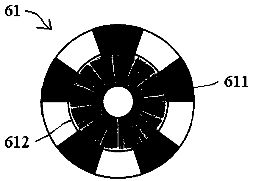
[0047] Please refer to Figure 1-6 , figure 1 It is a structural schematic diagram of a specific embodiment of the robot articulated arm provided by the present invention, figure 2 is a schematic structural diagram of the first encoder, image 3 for figure 2 left view of Figure 4 It is the connection structure diagram of the second encoder board, the second mounting seat and the flange shaft, Figure 5 It is the connection structure diagram of the driver board, the first encoder board and the second...


PUM


Abstract

The invention discloses a robot joint arm and a robot. The robot joint arm comprises a shell, and a motor is arranged in the shell the robot joint arm; further comprises a multiplex encoder, the multiplexing encoder is in an annular shape and the multiplexing encoder is arranged on a rotating shaft of the motor in a sleeved mode, the inner ring part of the multiplex encoder is a photoelectric encoder, and the outer ring part is a magnetic encoder. According to the robot joint arm, the optical encoder and the magnetic encoder which are independently arranged in the prior art are integrated intoa whole, the axial size of the motor can be greatly reduced, and the functional density of the motor can be improved, the axial size of the joint arm of the whole robot can be reduced, and the photoelectric encoder and the magnetic encoder cannot be influenced so that the multiplex encoder can simultaneously have the functions of detecting the rotating speed and position of the rotating shaft andthe phase change point of the motor.

Description

technical field [0001] The invention relates to the technical field of robots, in particular to a robot joint arm and a robot. Background technique [0002] There is a motor in the robot joint arm as a driving mechanism. In order to ensure the reliable operation of the motor, a photoelectric encoder and a magnetic encoder are usually installed. The photoelectric encoder is used to detect the speed and position of the motor rotor, and the magnetic encoder is used. Used to detect the commutation point of the motor. [0003] In the prior art, the photoelectric encoder and the magnetic encoder are installed independently, which leads to a larger axial dimension of the motor, which in turn leads to an increase in the axial dimension of the entire robot joint arm. [0004] Therefore, how to provide a robot articulated arm with a smaller axial dimension is still a technical problem to be solved urgently by those skilled in the art. Contents of the invention [0005] The object ...

Claims


Application Information

Patent Timeline
Patent Type & Authority Applications(China)
IPC IPC(8): B25J17/02B25J19/00B25J13/08
CPCB25J13/08B25J17/0258B25J19/00B25J19/0004B25J19/0054
Inventor 黄真牟联树李煜
Owner AUBO BEIJING ROBOTICS TECH CO LTD
Learn More