
Moving type material guiding groove

A guide chute, mobile technology, used in conveyors, conveyor objects, transportation and packaging, etc., can solve problems such as material flow obstruction, and achieve the effect of preventing material splashing

Pending Publication Date: 2018-10-19
张家港华兴能源工程有限公司
View PDF0 Cites 1 Cited by
  • Summary
  • Abstract
  • Description
  • Claims
  • Application Information

AI Technical Summary

Problems solved by technology

However, after the material guide trough is installed at the material drop point beyond the starting point of the conveyor belt, it hinders the flow of materials, and a large amount of material often overflows here.

Method used


Image

  • Moving type material guiding groove

Examples


Embodiment Construction

[0016] The technical solutions in the embodiments of the present invention will be described in detail below in conjunction with the accompanying drawings in the embodiments of the present invention. Obviously, the described embodiments are only some of the embodiments of the present invention, not all of them. Based on the embodiments of the present invention, all other embodiments obtained by persons of ordinary skill in the art without making creative efforts belong to the protection scope of the present invention.

[0017] In the description of the present invention, it should be noted that the terms "center", "upper", "lower", "left", "right", "vertical", "horizontal", "inner", "outer" etc. The indicated orientation or positional relationship is based on the orientation or positional relationship shown in the drawings, and is only for the convenience of describing the present invention and simplifying the description, rather than indicating or implying that the referred de...


PUM


Abstract

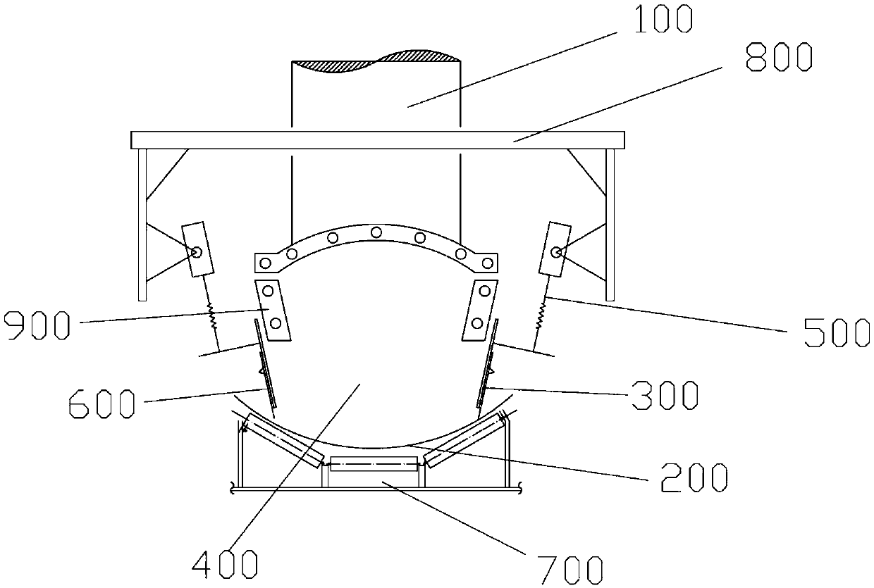
The application discloses a moving type material guiding groove, which is arranged on the outlet of a blanking pipe. The outlet of the blanking pipe is over against a conveyor belt, the outlet of theblanking pipe is oppositely provided with moving baffles at both sides of the conveyor belt, the upper ends of the moving baffles are inclined outwards, a material guiding groove is formed between thetwo oppositely arranged moving baffles, an electric push rod is fixedly mounted on the back of each moving baffle, and the electric push rods move along inclined directions of the moving baffles. Themoving type material guiding groove has the advantages that the moving baffles are lifted when materials are supplied, the conveying of the materials is not affected, and the moving baffles are descended when discharging is needed to prevent the materials from splashing.

Description

technical field [0001] The present application relates to a material conveying system, in particular to a mobile material guide chute. Background technique [0002] Belt conveyors are widely used in mining, metallurgy, electric power and other fields. For the power generation industry, coal blocking of belt conveyors often occurs. Once coal blocking occurs, manual intervention is usually too late, so it will affect the production of power plants if it is large, and waste a lot of manpower and material resources to deal with coal overflow if it is small. The traditional material guide troughs are all fixed installations, and the material is prevented from splashing and overflowing by adjusting the material guide skin. However, after the material guide trough is installed at the material drop point other than the starting point of the conveyor belt, it hinders the smooth flow of the material, and a large amount of material often overflows here. Contents of the invention ...

Claims


Application Information

Patent Timeline
IPC IPC(8): B65G47/20
CPCB65G47/20B65G2201/045
Inventor 季先忠
Owner 张家港华兴能源工程有限公司
Learn More