
Automatic automobile loading system for aggregate

An automotive and automatic technology, applied in the directions of transportation and packaging, loading/unloading, etc., can solve the problems of spilling outside the carriage, long loading time, and many post workers, to prevent dust spillage, prevent material splashing, and reduce post workers. Effect

Pending Publication Date: 2021-06-11
CITIC HEAVY INDUSTRIES CO LTD
View PDF0 Cites 0 Cited by
  • Summary
  • Abstract
  • Description
  • Claims
  • Application Information

AI Technical Summary

Problems solved by technology

[0002] As we all know, in order to prevent under-loading or overloading of the aggregate production line, the loading method is usually to set up a truck scale under the loading garage and equip a post worker to direct the loading; Gradually increase, and stop unloading after the height of the carriage is full; instruct the driver to move the vehicle frequently, then start the loading equipment again, repeat the above loading process until the car is full; after the car is full, the pile of materials in the carriage is in the form of multiple peaks , in order to prevent material spilling on the transportation road, the driver needs to manually level it out; and the valve controlling the unloading is often blocked, causing the material to spill outside the compartment during the loading process, which requires manual cleaning, which is time-consuming and laborious, pollutes the environment, and takes a long time for loading, which greatly Reduced labor efficiency; especially when the production scale is large, many sets of loading systems are required, and 20-30 loading commanders are required. There are many positions and labor costs increase; this manual loading method, It hinders the progress of automation and intelligence in the whole plant

Method used


Image

  • Automatic automobile loading system for aggregate

Examples


Embodiment Construction

[0016] The present invention can be explained in detail through the following examples, and the purpose of disclosing the present invention is to protect all technical improvements within the scope of the present invention.

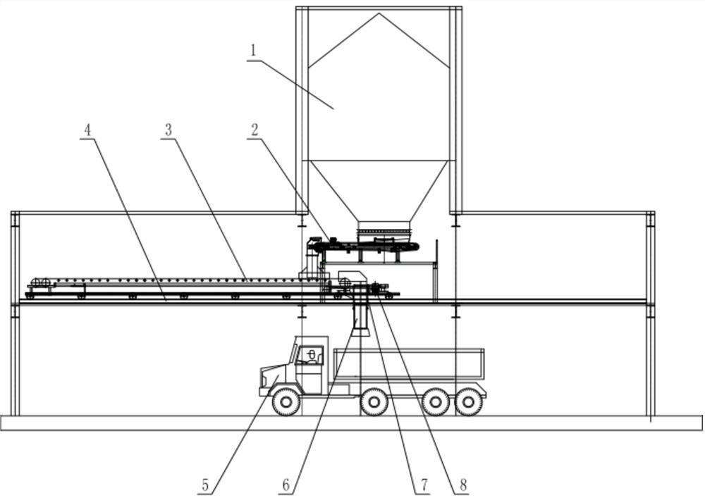
[0017] combined with figure 1 The automatic loading system for aggregate vehicles includes a loading bin 1 and a mobile loading machine, a quantitative feeder 2 is provided at the bottom of the outlet of the loading bin 1, and the mobile loading machine is arranged on the quantitative feeder 2. The lower part of the outlet end; the mobile loading machine includes a warehouse distribution belt conveyor 3, a walking track 4 and a mobile bulk head; the mobile bulk head is installed below the feeding hopper of the warehouse distribution belt conveyor 3; the mobile bulk head includes a telescopic feeding pipe 6 , steel wire rope 7 and winch 8, the feeding pipe 6 is a multi-section sleeve nested together, a suspension point is provided on the outermost sleeve, ...


PUM


Abstract

The invention discloses an automatic automobile loading system for aggregate, and relates to an automatic loading system. The system comprises a loading bin and a movable loading machine which are arranged in a loading plant, a constant feeder is arranged on the lower portion of a discharging port of the loading bin, the movable loading machine is arranged on the lower portion of the outlet end of the constant feeder, the movable loading machine comprises a warehouse belt conveyor, a walking track and a movable bulk head, the movable bulk head is arranged below a discharging hopper of the warehouse belt conveyor, the movable bulk head comprises a telescopic discharging pipe, a steel wire rope and a winch, the discharging pipe is formed by nesting a plurality of sleeves together, a suspension point is arranged on the sleeve on the outermost layer, and the winch is connected to the suspension point through the steel wire rope and is fixed to a head support of the warehouse belt conveyor. The system has the advantages of being simple and convenient to use, a driver does not need to move a vehicle many times, so that the burden of workers is greatly relieved, the number of posts is decreased, and therefore automatic and intelligent loading becomes possible.

Description

technical field [0001] The invention relates to an automatic loading system, in particular to an automatic loading system for aggregate vehicles. Background technique [0002] As we all know, in order to prevent under-loading or overloading of the aggregate production line, the loading method is usually to set up a truck scale under the loading garage and equip a post worker to direct the loading; Gradually increase, and stop unloading after the height of the carriage is full; instruct the driver to move the vehicle frequently, then start the loading equipment again, repeat the above loading process until the car is full; after the car is full, the pile of materials in the carriage is in the form of multiple peaks , in order to prevent material spilling on the transportation road, the driver needs to manually level it out; and the valve controlling the unloading is often blocked, causing the material to spill outside the compartment during the loading process, which requires...

Claims


Application Information

Patent Timeline
IPC IPC(8): B65G67/06
CPCB65G67/06
Inventor 李建功高源杜自彬刘俊焦舒亚闫昊天
Owner CITIC HEAVY INDUSTRIES CO LTD
Learn More