
Method for installing isolation fence

An installation method and isolation barrier technology, which can be applied to road safety devices, construction material processing, roads, etc., can solve the problems of unreliable installation and unsmooth installation line, and achieve the effect of firm installation, labor cost saving, and overall smoothness

Inactive Publication Date: 2018-10-19
国信紫晶科技(江苏)有限公司
View PDF6 Cites 3 Cited by
  • Summary
  • Abstract
  • Description
  • Claims
  • Application Information

AI Technical Summary

Problems solved by technology

[0002] Isolation fence, usually effectively isolates the on-site loop in the dangerous area from the control system in the safe area of ​​the main control room. It is mainly used for guardrail protection in areas such as roads, railways, airports, ports, residential quarters, and gardens. Safety needs, building perimeter protection is becoming more and more important. When it comes to the perimeter length mechanism, the labor cost will be higher, but the existing installation method of the isolation fence does not meet the specific needs, and the overall installation line is not smooth and not Compatible with terrain, not securely installed

Method used


Image

  • Method for installing isolation fence
  • Method for installing isolation fence

Examples


Embodiment 1

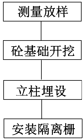
[0020] Embodiment one, combined with the attached figure 1 And attached figure 2 , a method for installing an isolation barrier, comprising a column 1 and an isolation barrier 2, is characterized in that it includes the following steps:

[0021] a. Measurement and stakeout, survey and measure the construction site, set the ground repair in a ladder shape, stake out and mark, after locating the position of column 1 in the center, determine other column positions according to the column distance, and mark them with wooden stakes;

[0022] b. For the excavation of concrete foundation, set up concrete foundation II at the corner of the straight line, set up concrete foundation IV at the end of the straight line, set up concrete foundation I, concrete foundation II, and concrete foundation III every 20m on the straight line, Concrete foundation IV: Excavate the foundation pit, tamp the foundation, and check the axis and spacing on the same straight line;

[0023] c. For column e...

Embodiment 2

[0029] Embodiment two, according to the attached figure 1 , the material of the isolation grid 2 is set as low-carbon steel wire of φ3.5mm, the isolation grid 2 is made of steel plate and iron wire, the central sag after the iron wire is tightened and fixed is less than 15mm, and each column 1 The bending degree shall not exceed 8mm / m. Galvanized and plastic-coated anti-corrosion materials are respectively provided on the outer wall of the isolation grid 2 from the inside to the outside. Polyethylene or polyester, the material of the plastic layer of the isolation grid 2 is polyethylene, and the thickness of the plastic layer is 0.3mm. The material of the plastic layer of the isolation grid 2 is polyester, and the thickness of the plastic layer is 0.1mm. The columns 1 are all cast-in-place with C26 concrete.

[0030] The isolation fence 2 made of steel plate and iron wire should be flat after installation, without obvious warping and unevenness. Deformation, curling or scrat...


PUM


Abstract

The invention discloses a method for installing an isolation fence. The method comprises upright columns and the isolation fence, and is characterized by comprising the steps of performing measurementand lofting, excavating concrete foundations, burying the upright columns and installing the isolation fence. The method for installing the isolation fence according to the invention has the beneficial effects of saving the time cost, saving the labor cost particularly for a mechanism relating to perimeter length, enabling the installation position of the isolation fence to meet the requirements,enabling an overall installation line shape to be smooth and to coordinate with terrain, enabling the enclosure to be tight and enabling the installation to be firm.

Description

technical field [0001] The invention relates to the technical field of object prevention, in particular to the field of an installation method of an isolation barrier. Background technique [0002] Isolation fence, usually effectively isolates the on-site loop in the dangerous area from the control system in the safe area of ​​the main control room. It is mainly used for guardrail protection in areas such as roads, railways, airports, ports, residential quarters, and gardens. Safety needs, building perimeter protection is becoming more and more important. When it comes to the perimeter length mechanism, the labor cost will be higher, but the existing installation method of the isolation fence does not meet the specific needs, and the overall installation line is not smooth and not In harmony with the terrain, the installation is not secure. Contents of the invention [0003] In order to solve the above problems, the present invention has developed a method for installing ...

Claims


Application Information

Patent Timeline
Patent Type & Authority Applications(China)
IPC IPC(8): E01F15/02E04G21/00
CPCE01F15/02E04G21/00
Inventor 席修建
Owner 国信紫晶科技(江苏)有限公司
Learn More