
Coaxial linear speed changing mechanism

A speed change mechanism and coaxial technology, applied in the direction of mechanical equipment, gear transmission, belt/chain/gear, etc., can solve problems such as stuck joints, irregular sizes, etc.

Pending Publication Date: 2018-10-19
樊朝晖
View PDF0 Cites 2 Cited by
  • Summary
  • Abstract
  • Description
  • Claims
  • Application Information

AI Technical Summary

Problems solved by technology

[0007] The purpose of the present invention is to provide a coaxial linear transmission mechanism, which realizes the coaxial linear design of the output shaft of the two-stage transmission mechanism of electric vehicles and the input shaft of the motor, which can not only directly integrate with various motors, but also solve the problem of traditional off-axis The problem of the abnormal size of the speed change mechanism and the problem of various jams during the speed change process

Method used


Image

  • Coaxial linear speed changing mechanism
  • Coaxial linear speed changing mechanism
  • Coaxial linear speed changing mechanism

Examples


Embodiment 1

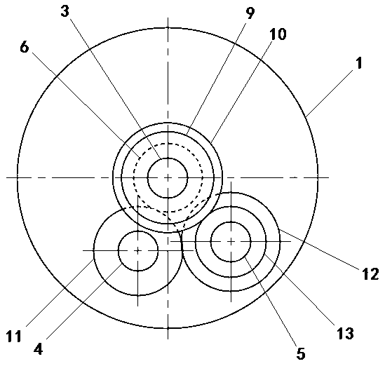
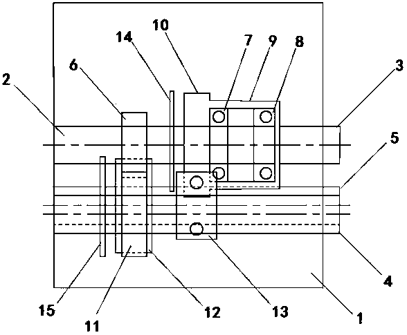
[0039] see figure 1 and figure 2 As described above, a coaxial linear transmission mechanism includes a housing 1, an input shaft 2, an output shaft 3, a transition shaft 4 and a low-speed transmission shaft 5, and the input shaft 2, the transition shaft 4 and the low-speed transmission shaft 5 are in pairs are arranged parallel to each other in the housing 1 .

[0040] The input shaft 2 is connected to the motor, and can rotate counterclockwise or clockwise with the motor. The input shaft 2 is provided with a first transmission gear 6 and a one-way conjoined gear. The first transmission gear 6 It is fixedly connected with the input shaft 2. The one-way conjoined gear is composed of a bearing inner ring and a gear casing sheathed together. The bearing inner ring includes a supporting bearing 7 and a one-way bearing 8 arranged side by side. The gear casing includes a front casing connected together. Gear 9 and rear gear 10 of the outer casing.

[0041] The front end of the...

Embodiment 2

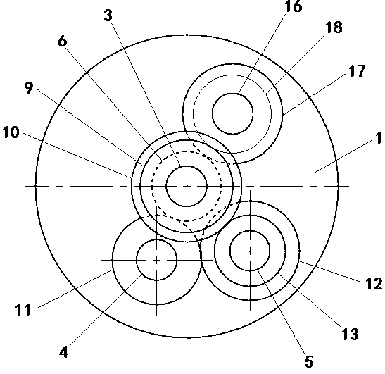
[0048] see image 3 and Figure 4 As shown, in order to meet the reverse gear requirements of four-wheel electric vehicles, on the basis of Embodiment 1, a reverse transmission shaft 16 parallel to the input shaft 2 is also provided in the housing 1, and the reverse gear The transmission shaft 16 is sleeved with a third transmission gear 17 and a fourth transmission gear 18, the third transmission gear 17 is movably connected with the reverse transmission shaft 16, the fourth transmission gear 18 is connected with the reverse transmission The shaft 16 is fixedly connected. The third transmission gear 17 is meshed with the first transmission gear 6 , and the fourth transmission gear 18 is meshed with the front gear 9 of the one-way conjoined gear. The diameter of the third transmission gear 17 is larger than the diameter of the first transmission gear 6, the diameter of the fourth transmission gear 18 is smaller than the diameter of the third transmission gear 17, and the fir...


PUM


Abstract

The invention discloses a coaxial linear speed changing mechanism. The coaxial linear speed changing mechanism comprises an input shaft, an output shaft, a transition shaft and a low-speed transmission shaft. The input shaft is provided with a first transmission gear and a one-way connected gear. The front end of the input shaft is arranged in the one-way connected gear, and the output shaft is arranged on the front side end face of the one-way connected gear and is coaxial to the input shaft. The transition shaft is provided with a transition gear. The low-speed transmission shaft is providedwith a second transmission gear and a one-way gear. The transition gear is engaged with the first transmission gear and the second transmission gear. The one-way gear and the one-way connected gear are engaged and are opposite in effective rotation direction. The one-way connected gear and the second transmission gear are fixedly connected with the input shaft and a low-speed-gear transmission shaft through coaxial clamping and connecting discs correspondingly. According to the coaxial linear speed changing mechanism, the motor forward rotation and reverse rotation equivalence principle is sufficiently utilized, speed changing box design is conducted in the coaxial linear direction through the two-one-way-gear both-way clutch manner, the coaxial linear speed changing mechanism can be directly fused with various motors, and meanwhile the problem about the special-shape size of traditional off-axis speed changing mechanisms can be solved.

Description

technical field [0001] The invention belongs to the technical field of speed change mechanisms, and in particular relates to a special coaxial linear speed change mechanism for electric vehicles. Background technique [0002] Electric vehicles are about to become a new means of transportation that is popular all over the world, and the models of various electric vehicles are too numerous to mention. But there is a problem with all electric vehicles, that is, whether a gearbox is required. So far, including the famous Tesla electric vehicles and Toyota electric vehicles, they all adopt the direct drive mode of electric motors for power drive. The characteristic of the motor direct drive method is that the motor is directly driven by a high-speed motor or driven by a reduction ratio to drive the car. Its advantage is to give full play to the characteristics of the high-speed motor. For example, the motor speed of a Tesla electric car is as high as 12,000 revolutions per minut...

Claims


Application Information

Patent Timeline
Patent Type & Authority Applications(China)
IPC IPC(8): F16H3/10
CPCF16H3/10
Inventor 樊朝晖左臣伟李新民
Owner 樊朝晖
Learn More