Novel adjustable throttle valve
A throttling valve, adjustable technology, applied in the direction of lift valves, valve devices, engine components, etc., can solve the problems of loss of fluid regulation, valve core failure, accidents, etc., to achieve uniform force, stable regulation of fluid flow, and overall The effect of structural stability
- Summary
- Abstract
- Description
- Claims
- Application Information
AI Technical Summary
Problems solved by technology
Method used
Image
Examples
Embodiment 1
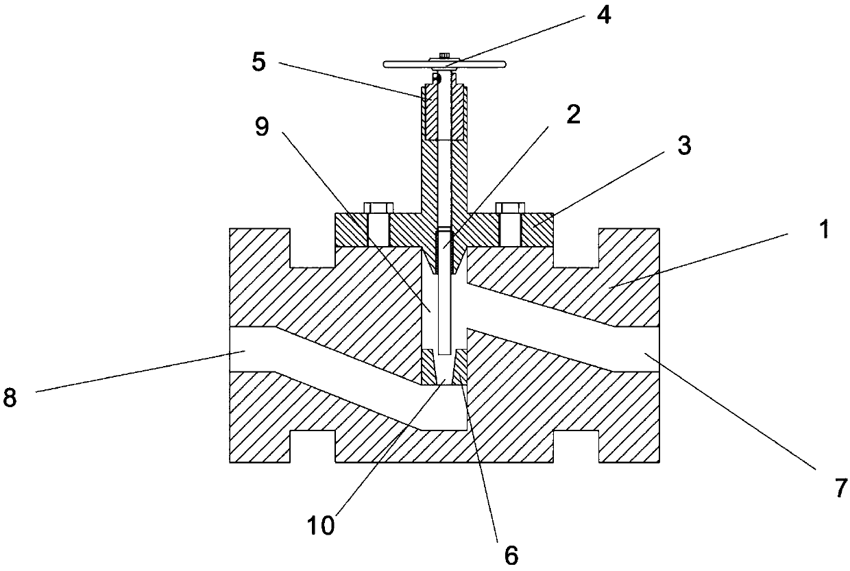
[0027] Such as figure 1 As shown, Embodiment 1 of the present invention discloses an adjustable throttle valve, which includes a valve body 1, a valve core 2, a valve cover 3, an adjustment hand wheel 4, an opening display sleeve 5 and a valve seat 6, and the inside of the valve body 1 A fluid inlet 7, a fluid outlet 8 and a spool cavity 9 are provided, and the spool cavity 9 communicates with the fluid inlet 7 and the fluid outlet 8 through a flow channel; one end of the spool 2 is inserted into the spool cavity 9, and the other end is inserted into the valve The cover 3 is coaxially connected with the adjusting handwheel 4, the valve core 2 is a cylindrical structure as a whole; the valve cover 3 is fixedly connected with the valve body 1, and an opening display sleeve 5 is set between the valve cover 3 and the adjusting handwheel 4; the valve seat 6 is arranged at the bottom of the spool cavity 9, and the valve seat 6 is provided with a conical cavity 10, which is coaxially...
Embodiment 2
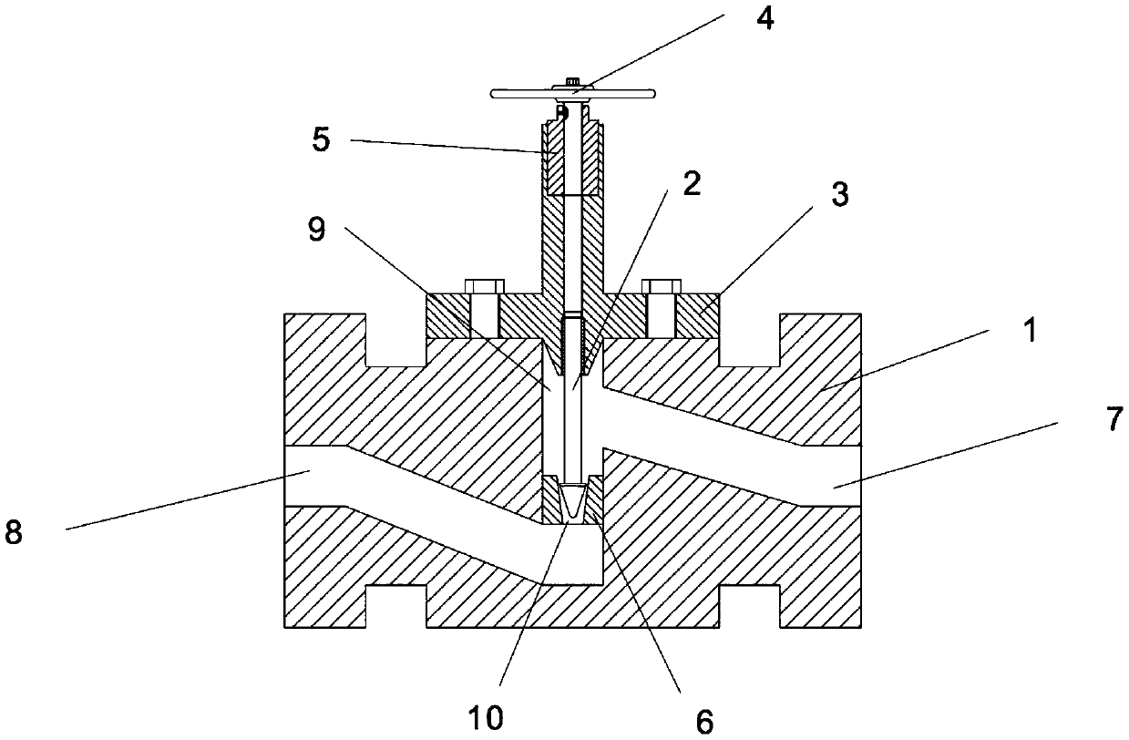
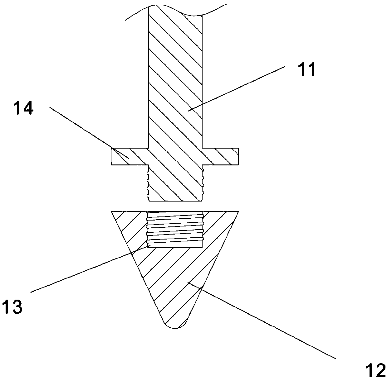
[0030] Such as Figure 2-3 As shown, Embodiment 2 of the present invention discloses an adjustable throttle valve, which includes a valve body 1, a valve core 2, a valve cover 3, an adjustment hand wheel 4, an opening display sleeve 5 and a valve seat 6. Inside the valve body 1 A fluid inlet 7, a fluid outlet 8 and a spool cavity 9 are provided, and the spool cavity 9 communicates with the fluid inlet 7 and the fluid outlet 8 through a flow channel; one end of the spool 2 is inserted into the spool cavity 9, and the other end is inserted into the valve The cover 3 is coaxially connected with the adjusting handwheel 4; the valve cover 3 is fixedly connected with the valve body 1, and the opening degree display sleeve 5 is arranged between the valve cover 3 and the adjusting handwheel 4; the valve seat 6 is arranged at the bottom of the valve core cavity 9 , the valve seat 6 is provided with a frustum-shaped cavity 10 inside, the frustum-shaped cavity 10 is coaxially arranged wi...
PUM
 Abstract
Description
Claims
Application Information
 - R&D
- Intellectual Property
- Life Sciences
- Materials
- Tech Scout
- Unparalleled Data Quality
- Higher Quality Content
- 60% Fewer Hallucinations
Browse by: Latest US Patents, China's latest patents, Technical Efficacy Thesaurus, Application Domain, Technology Topic, Popular Technical Reports.
© 2025 PatSnap. All rights reserved.Legal|Privacy policy|Modern Slavery Act Transparency Statement|Sitemap|About US| Contact US: help@patsnap.com


