
Machine tool capable of realizing rapid vibration

A kind of machine tool and fast technology, applied in the field of machinery, can solve the problems of slow vibration motor speed and poor efficiency of screening materials, etc., and achieve the effect of solving the speed too slow

Inactive Publication Date: 2018-10-23
李丽倩
View PDF0 Cites 0 Cited by
  • Summary
  • Abstract
  • Description
  • Claims
  • Application Information

AI Technical Summary

Problems solved by technology

[0005] Aiming at the deficiencies of the prior art, the present invention provides a fast-vibrating machine tool, which has the advantages of fast vibration, and solves the problem that the speed of the vibration motor using the spring is too slow and the efficiency of screening materials cannot be improved

Method used

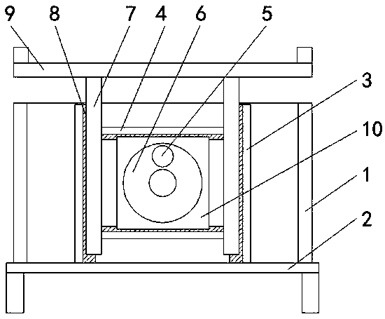
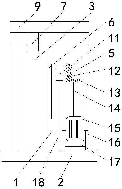

Image

  • Machine tool capable of realizing rapid vibration
  • Machine tool capable of realizing rapid vibration

Examples


Embodiment Construction

[0020] The following will clearly and completely describe the technical solutions in the embodiments of the present invention with reference to the accompanying drawings in the embodiments of the present invention. Obviously, the described embodiments are only some, not all, embodiments of the present invention. Based on the embodiments of the present invention, all other embodiments obtained by persons of ordinary skill in the art without making creative efforts belong to the protection scope of the present invention.

[0021] see Figure 1-2 , a fast vibrating machine tool, comprising an outer box 1, a base 2 is fixedly installed on the bottom of the outer box 1, and two fixed rods 3 are fixedly installed on the top of the base 2 and located inside the outer box 1, and one of the fixed rods 3 is opposite A movable column 7 is arranged on the side, and the top of the movable column 7 extends to the top of the outer box 1, and the top of the movable column 7 is fixedly equippe...


PUM


Abstract

The invention relates to the technical field of machinery, and discloses a machine tool capable of realizing rapid vibration. The machine tool capable of realizing rapid vibration comprises an outer box, wherein a base is fixedly installed at the bottom of the outer box; two fixed rods are fixedly installed at the top of the base and in the outer box; movable columns are arranged at the opposite sides of each fixed rod; a vibration plate is fixedly installed at the tops of the movable columns; two fixed plates are connected to the opposite sides of the movable columns; a movable groove is formed in the opposite sides of the two fixed plates and the opposite sides of the two fixed rods separately; and a movable block is clamped between the two fixed plates. According to the machine tool capable of realizing rapid vibration, through arrangement for a fixing ring on a first rotary shaft, the first rotary shaft can be supported; and through arrangement for a vertical gear on the first rotary shaft and engaged with a cross gear, the rotation of the vertical gear can be driven during the rotation of a motor, so that the problem that the efficiency of screening goods and materials cannotbe increased due to a too low speed of the vibration motor utilizing a spring, is effectively solved.

Description

technical field [0001] The invention relates to the technical field of machinery, in particular to a fast-vibrating machine tool. Background technique [0002] Vibrating machinery is mechanical vibration transmitted through an elastic medium, and the reciprocating motion of an object or particle near its equilibrium position. The motion of a table tennis ball is a mechanical motion because there is a balance position, circular or elliptical vibration: the vibration track of the vibrating body is in The projection on the horizontal plane is a straight line, while the projection on the vertical plane is a circle or ellipse, and its vibration form is called circular or elliptical vibration. Usually, a vibration motor is installed on the vibration machine body to generate this vibration. The circular or elliptical vibration occurs on a plane perpendicular to the vibration motor shaft, and its form depends on the relative position of the vibration motor and the center of gravity ...

Claims


Application Information

Patent Timeline
IPC IPC(8): B07B1/34B07B1/42
CPCB07B1/343B07B1/42
Inventor 李丽倩
Owner 李丽倩
Learn More