Packaging bag binding machine
A packaging bag and strapping machine technology, which is applied in the direction of packaging/binding items, packaging, and strapping machine parts, etc., can solve the problems of health hazards for workers, high production costs, and high error rates in strapping operations, and achieve low cost, The effect of complete separation and simple structure
- Summary
- Abstract
- Description
- Claims
- Application Information
AI Technical Summary
Problems solved by technology
Method used
Image

Examples
Embodiment 1
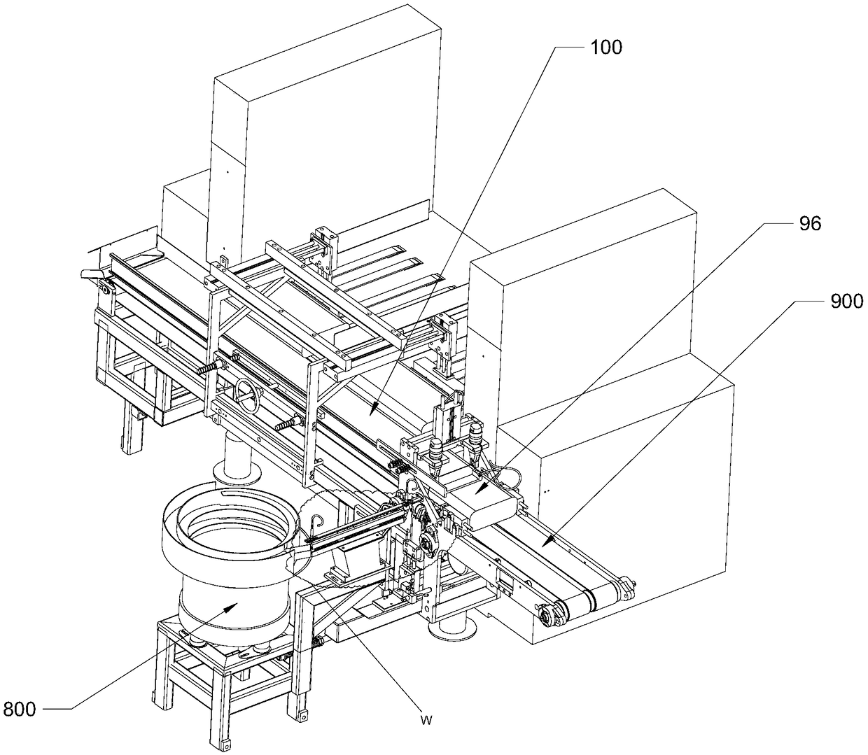
[0035] A packaging bag binding machine, including a rubber band screening device, a rubber band stretching device and a packaging bag conveying device, wherein:
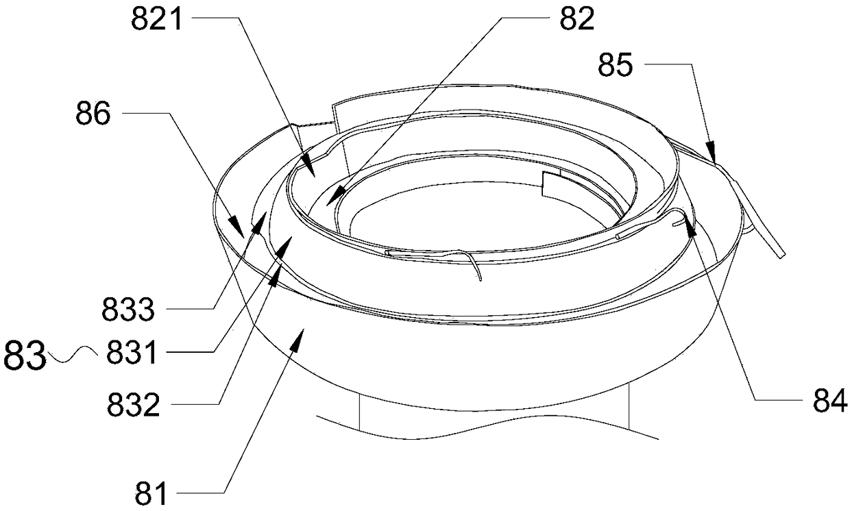
[0036] Elastic screening unit including vibrating disc, see Figure 1-Figure 3 , the vibrating plate includes a hopper 81 and a feeding track 82, the outer edge of the feeding track 82 is fixed on the inner wall of the hopper 81, the feeding track 82 spirals up, the vibrating plate works, the rubber band at the bottom of the hopper 81 spirals up through the feeding track 82, and the feeding The upper end of the track 82 is provided with a feed port 821, and the rubber band is delivered to the outside of the feed track 82 through the feed port 821 (the outside refers to the area between the outer edge of the feed track 82 and the inner wall of the hopper 81), and the outside of the feed track 82 is fixed with a screening track 83, the screening track 83 is located outside the feeding port 821, whereby the rubber band ...
Embodiment 2
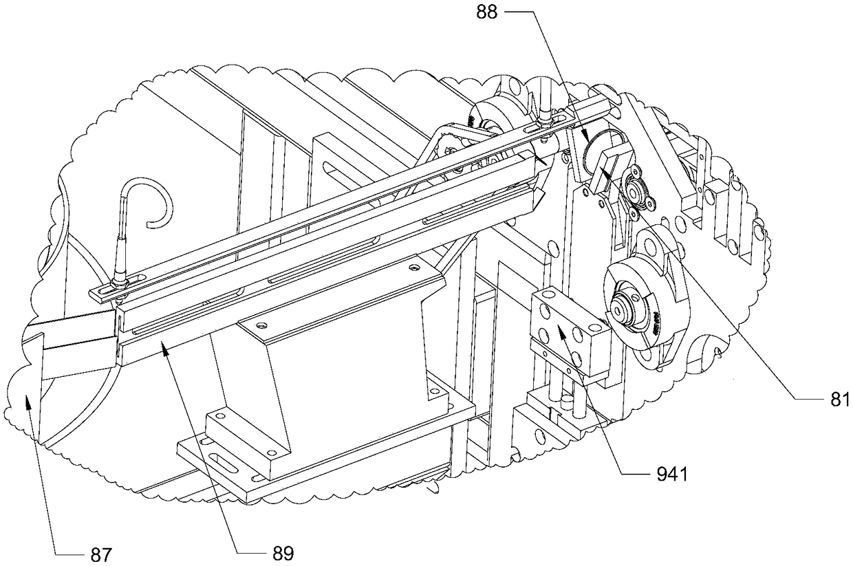
[0050] see Figure 4-Figure 8 The rubber band stretching device includes a frame, a rubber band gripper 91, a horizontal stretching mechanism and a vertical stretching mechanism, and the rubber band gripper 91 is slidably installed on the frame along the vertical direction and the front and rear direction, and the rubber band gripper is slidably mounted on the frame. 91 has a rubber band clamping part that can clamp and loosen the rubber band; the horizontal expansion mechanism includes two pins 92 that are slidably installed on the frame along the left and right directions; The support rubber band gripper 93 that is installed on the frame, the support rubber band gripper 93 has the support rubber band clamping part that can clamp and loosen the rubber band, the support rubber band gripper 93 is positioned at the top of described pin 92, cover rubber band clip The hand 91 is located below the pin 92 .
[0051] Cover rubber band gripper 91 clamps an end of rubber band 6, make ...
Embodiment 3
[0058] On the basis of Embodiment 2, the inventor found that because the first end 921 of the pin 92 is suspended in the air, it is easy to sag under the action of its own weight, and it is easy to bend toward each other under the pressure of the periodic rubber band. Both situations are unfavorable to the insertion of the pin 92, so in order to avoid the occurrence of the above situation, the invention also includes a supporting member installed on the frame, the supporting member is arranged under the pin 92, so that the pin 92 The upward support prevents the first end 921 of the insertion pin 92 from sagging under the action of its own weight. The supporting member has a friction part that is in contact with the lower surface of the insertion pin 92. In addition, when the insertion pin 92 sags, the insertion pin 92 It is bound to form friction with the supporting member. Obviously, this friction will increase the movement resistance of the pin 92 and cause unidirectional wea...
PUM
 Abstract
Description
Claims
Application Information
 - R&D
- Intellectual Property
- Life Sciences
- Materials
- Tech Scout
- Unparalleled Data Quality
- Higher Quality Content
- 60% Fewer Hallucinations
Browse by: Latest US Patents, China's latest patents, Technical Efficacy Thesaurus, Application Domain, Technology Topic, Popular Technical Reports.
© 2025 PatSnap. All rights reserved.Legal|Privacy policy|Modern Slavery Act Transparency Statement|Sitemap|About US| Contact US: help@patsnap.com