Unpowered roller for conveying

A roller and power technology, applied in the field of non-powered rollers, can solve problems such as difficulty in improving work efficiency and inconvenience

Inactive Publication Date: 2018-10-23
湖州银轴智能装备有限公司
View PDF7 Cites 4 Cited by
  • Summary
  • Abstract
  • Description
  • Claims
  • Application Information

AI Technical Summary

Problems solved by technology

However, the currently commonly used roller conveyors are mostly planar structures. When it is necessary to change the conveying direction of workpieces or goods, raise and lower the conveying angle of goods or workpieces, or convey larger-sized workpieces or goods, it is necessary to replace the corresponding unpowered roller conveyor. Machine, very inconvenient, difficult to improve work efficiency

Method used


Image

  • Unpowered roller for conveying
  • Unpowered roller for conveying
  • Unpowered roller for conveying

Examples


Embodiment Construction

[0019] The present invention is not limited by the following examples, and specific implementation methods can be determined according to the technical solutions of the present invention and actual conditions.

[0020] Below in conjunction with embodiment and accompanying drawing, the present invention will be further described:

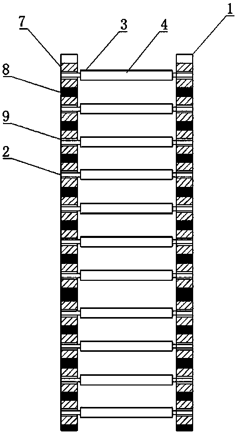
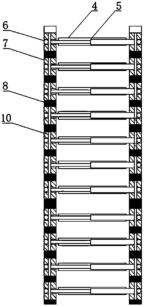
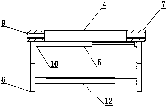
[0021] Such as figure 1 , 2 , 3, 4, 5, 6, 7, 8, a kind of unpowered roller for conveying, including a long arm horizontal frame 1, a rotating shaft 2, a roller 4 with a casing 3, a horizontal hydraulic device 5, a vertical To the hydraulic device 6, the long arm cross frame 1 includes a fixed block 7 and a flexible connection device 8 between the two fixed blocks 7, the fixed block 7 is fixedly connected to the flexible connection device 8, and the two ends of the rotating shaft 2 pass through The bearing 9 is installed on the fixed block 7, and the roller 4 is fixedly installed on the rotating shaft 2. The roller 4 includes a left half roller 41 a...


PUM


Abstract

The invention belongs to the field of conveying devices, and particularly relates to an unpowered roller for conveying. The unpowered roller comprises long arm cross arms, rotary shafts, rollers withsleeves, transverse hydraulic devices and vertical hydraulic devices. The long arm cross arms comprise fixing blocks and flexible connecting devices between the fixing blocks. The two ends of the rotary shafts are mounted on the fixing blocks through bearings, the rollers are fixedly mounted on the rotary shafts, the rollers comprise left half rollers and right half rollers, and the left half rollers and the right half rollers are in penetrating-inserting connection through splines. One ends of the transverse hydraulic devices are fixedly mounted on the lower faces of the fixing blocks throughfixing plates, the other ends of the transverse hydraulic devices are fixedly mounted on the lower faces of the corresponding fixing blocks through fixing plates, and the vertical hydraulic devices are fixedly mounted on the lower faces of the fixing blocks and located on the outer sides of the fixing plates. The lengths of the rollers are adjusted through the transverse hydraulic devices and theconveying height is adjusted through the vertical hydraulic devices, the conveying requirements of workpieces or cargoes of different sizes are met, and the beneficial effects of being high in practicality and high in working efficiency are achieved.

Description

technical field [0001] The invention belongs to the field of conveying devices, in particular to a non-powered roller used for conveying. Background technique [0002] In the multi-step production process, it is often necessary to transfer workpieces or goods from one section to the next or from one direction to another in a short distance. The unpowered roller conveyor transports goods by means of rolling friction, which can save a lot manpower. However, the currently commonly used roller conveyors are mostly planar structures. When it is necessary to change the conveying direction of workpieces or goods, raise and lower the conveying angle of goods or workpieces, or convey larger-sized workpieces or goods, it is necessary to replace the corresponding unpowered roller conveyor. Machine, very inconvenient, difficult to improve work efficiency. Contents of the invention [0003] In view of the above-mentioned technical problems, the purpose of the present invention is to ...

Claims


Application Information

Patent Timeline
Patent Type & Authority Applications(China)
IPC IPC(8): B65G13/04B65G13/12B65G41/00
CPCB65G13/04B65G13/12B65G41/003
Inventor 陈小杰
Owner 湖州银轴智能装备有限公司
Why Eureka
Try Eureka