
Supporting system and engineering machine with same

A technology of construction machinery and support system, applied in the directions of pillars, cranes, bottom support structures, etc., can solve the problems of difficulty in ensuring the height of the chassis from the ground, and it is difficult to ensure the effective support of the tail of the chassis, so as to improve the anti-overturning ability and supporting ability. , the effect of a wide range of applications

Active Publication Date: 2012-07-18
SANY AUTOMOBILE MFG CO LTD
View PDF9 Cites 16 Cited by
  • Summary
  • Abstract
  • Description
  • Claims
  • Application Information

AI Technical Summary

Problems solved by technology

However, the concrete pump truck with this structure has the following technical problems: Generally, the longer the boom of the concrete pump truck, the longer the corresponding chassis and the larger area of ​​the corresponding center of gravity circle. In order to ensure the stability of the whole vehicle, the support The legs and arms must be longer to ensure that the shortest distance between the adjacent support points and the circumference of the center of gravity remains within the predetermined safety range
When the outrigger arm is stretched out, under the action of gravity, there must be an upturning phenomenon (there is a gap between the outer arm and the inner arm of the telescopic arm), if the length of the chassis is long, under the action of the self-weight of the chassis, the It is difficult to ensure that the tail of the chassis is effectively supported by the outriggers, so it is difficult to ensure the height of the chassis from the ground

Method used


Image

  • Supporting system and engineering machine with same
  • Supporting system and engineering machine with same
  • Supporting system and engineering machine with same

Examples


Embodiment Construction

[0036] The core of the present invention is to provide a supporting system, which can support the whole vehicle more stably. Another core of the present invention is to provide a construction machine with the above support system.

[0037] In order to enable those skilled in the art to better understand the technical solution of the present invention, the present invention will be further described in detail below in conjunction with the accompanying drawings and specific embodiments.

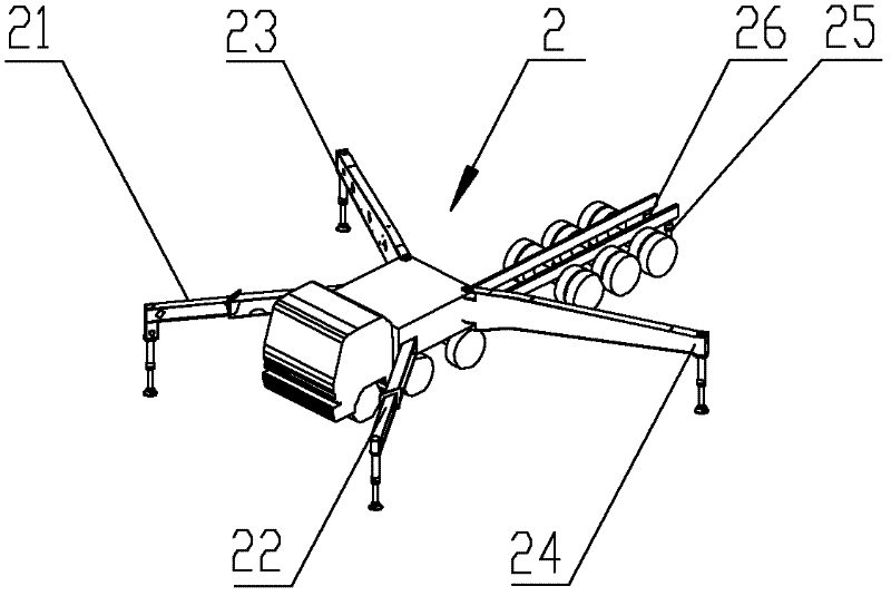
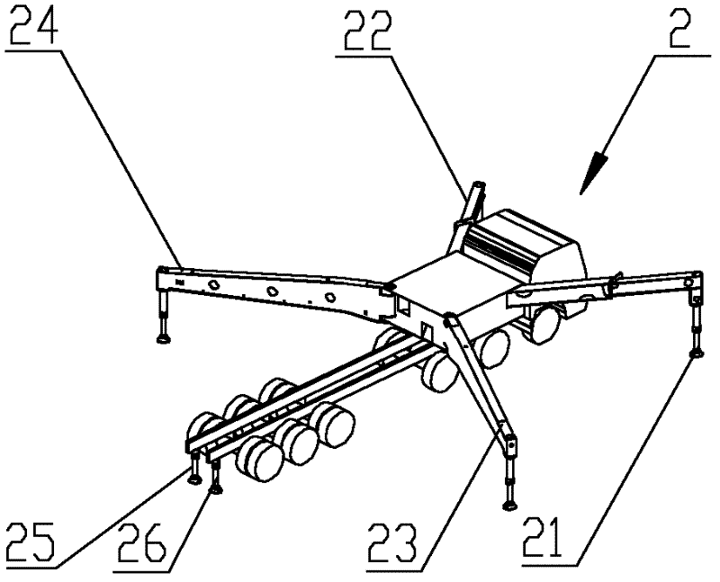
[0038] Please refer to Figure 2 to Figure 4 , figure 2 It is a schematic structural diagram of the first specific embodiment of the application of the support system provided by the present invention in construction machinery, which is viewed from the head of the chassis; image 3 for figure 2 Schematic diagram of the structure from the perspective of the rear of the chassis; Figure 4 for figure 2 top view.

[0039] The supporting legs provided by the present invention include a firs...


PUM


Abstract

The invention discloses a supporting system of an engineering machine, which comprises a first supporting leg, a second supporting leg, a third supporting leg and a fourth supporting leg which are arranged on the engineering machine. Additional supporting legs are arranged between the third supporting leg and the fourth supporting leg, and the minimum distance from a ligature of a supporting point of the third supporting leg and a supporting point of the fourth supporting leg to the circumference of a gravity center circle of the engineering machine is shorter than the minimum distance from a ligature of supporting points of each two adjacent of the third supporting leg, the fourth supporting leg and the additional supporting legs to the circumference of the gravity center circle of the engineering machine. By the aid of the additional supporting legs, anti-tipping capacity and supporting capacity of a whole vehicle are improved, and when being shortened, the supporting legs do not need to occupy sites with large site and can keep stability as same as those in the prior art, so that the engineering machine with the supporting system can be operated in limited space and meet construction needs of the narrow sites, and the application range of the engineering machine is widened. The invention further discloses the engineering machine comprising the supporting system.

Description

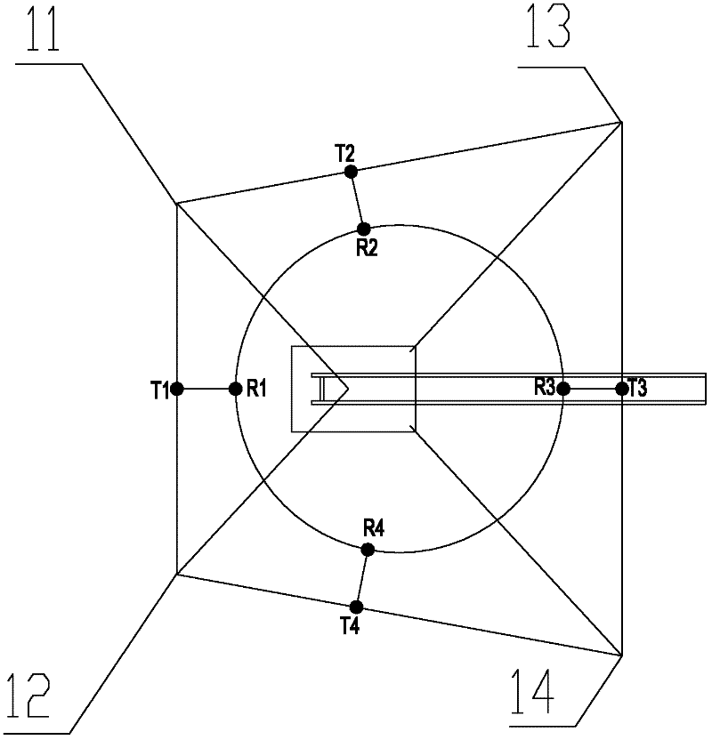
technical field [0001] The invention relates to the technical field of engineering machinery, in particular to a support system. The invention also relates to a construction machine with a support system as described above. Background technique [0002] Construction machinery usually has a support system to support the entire vehicle and drive the entire vehicle. Taking a concrete pump truck as an example, its support system generally includes four outriggers located on a fixed turret. During operation, two outriggers protrude forward and the other two outriggers protrude backward. [0003] Please refer to figure 1 , figure 1 It is a schematic diagram of the distribution of outriggers of a concrete pump truck in the prior art, and the figure also shows the relationship between the polygon formed by the support points of the outriggers and the stability of the vehicle body. [0004] The support system of the concrete pump truck is provided with a first front outrigger 11 ...

Claims


Application Information

Patent Timeline
Patent Type & Authority Applications(China)
IPC IPC(8): B60S9/10E04G21/04
CPCB66C23/78B66C5/00B60S9/10B66C23/80B66C23/905E04G21/04E04G25/00
Inventor 易小刚刘志斌陈鼎星
Owner SANY AUTOMOBILE MFG CO LTD
Learn More