Axial Fan Training Model
A technology of axial flow fan and model, which is applied in mine/tunnel ventilation, mining equipment, earthwork drilling and mining, etc., can solve problems such as lack of on-site experience of maintenance workers, low safety, and influence on mine safety production, so as to cultivate operation experience and feel effect
- Summary
- Abstract
- Description
- Claims
- Application Information
AI Technical Summary
Problems solved by technology
Method used
Image
Examples
Embodiment approach 1
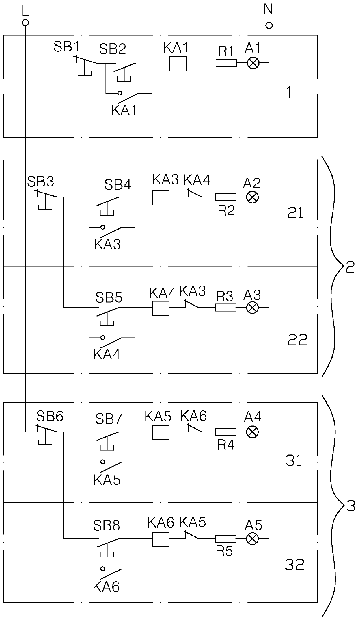
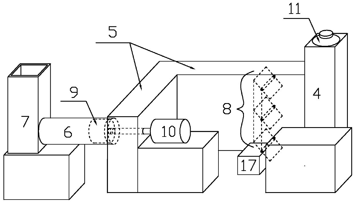
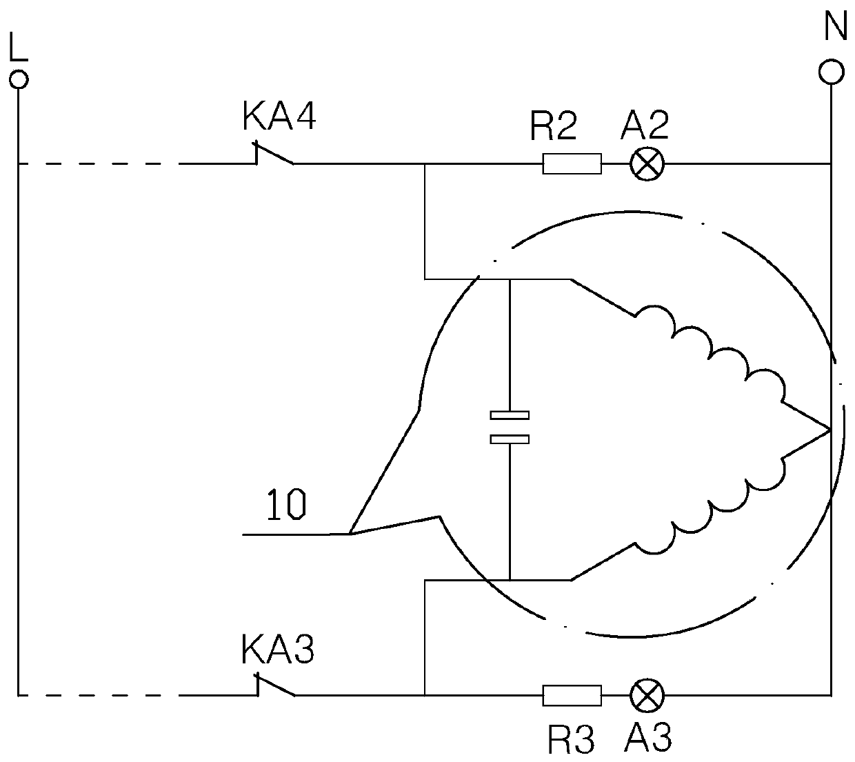
[0028] Implementation mode one: if Figure 1-3 As shown, the axial flow fan training model includes an axial flow fan control circuit, and the axial flow fan control circuit includes a hydraulic pump station manual control analog circuit 1, a fan manual control analog circuit 2, and a damper manual control analog circuit 3. It is characterized in that: Including air shaft model 4, air channel box 5, diffusion cylinder 6, diffusion tower model 7, the above components are connected in sequence, and the end of the air channel box 5 adjacent to the air shaft model 4 is provided with a damper 8,
[0029] The hydraulic pump station manual control analog circuit 1 includes a normally closed button switch SB1, a normally open button switch SB2, a normally open relay switch KA1, a resistor R1 and a hydraulic station indicator light A1, and the normally open relay switch KA1 includes a normally open armature switch And the coil, wherein the normally open armature switch of the normally ...
Embodiment approach 2
[0049] Implementation mode two: if Figure 4 As shown, the axial flow fan training model also includes PLC, manual switches K1, K2 and normally closed relay switch KA2, the normally closed relay switch KA2 includes a normally closed armature switch and a coil, and the PLC includes at least five module switches 12 , 13, 14, 15, 16, after the normally closed button switches SB1, SB3, SB6 are interconnected, the normally closed armature switch of the normally closed relay switch KA2 and the manual switch K1 are connected to the live wire L of the power supply, and the PLC After the five modular switches 12, 13, 14, 15, 16 are connected in parallel, they are connected to the fire wire L of the power supply through the manual switch K2.
[0050] The other end of the module switch 12 is connected to the contact between the normally open armature switch of the normally open relay switch KA1 and the coil; the other end of the module switch 13 is connected to the contact between the no...
PUM
 Abstract
Description
Claims
Application Information
 - R&D
- Intellectual Property
- Life Sciences
- Materials
- Tech Scout
- Unparalleled Data Quality
- Higher Quality Content
- 60% Fewer Hallucinations
Browse by: Latest US Patents, China's latest patents, Technical Efficacy Thesaurus, Application Domain, Technology Topic, Popular Technical Reports.
© 2025 PatSnap. All rights reserved.Legal|Privacy policy|Modern Slavery Act Transparency Statement|Sitemap|About US| Contact US: help@patsnap.com


