Installation structure of fuel injection valve
A technology of fuel injection valve and structure, which is applied in the direction of fuel injection devices, charging systems, engine components, etc., which can solve the problems of increased manufacturing costs, complex structures of cylinder heads or cages, and heat dissipation parts, and achieve suppression of high temperature, Effect of suppressing increase in manufacturing cost
- Summary
- Abstract
- Description
- Claims
- Application Information
AI Technical Summary
Problems solved by technology
Method used
Image

Examples
no. 1 approach 》
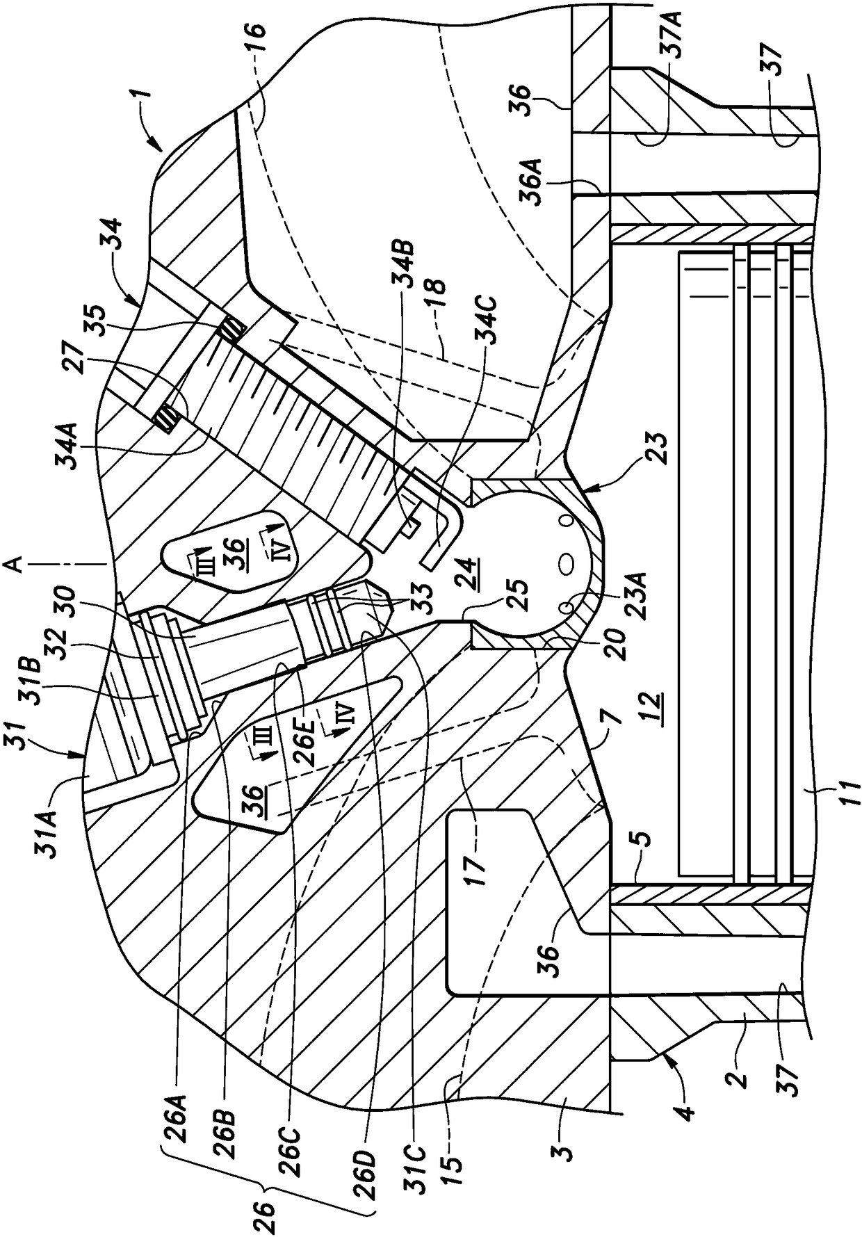
[0045] refer to Figure 1 ~ Figure 4 , First, the first embodiment will be described. figure 1 It is a schematic sectional view of the sub-chamber internal combustion engine of the first embodiment. Such as figure 1 As shown, the internal combustion engine 1 has an engine body 4 comprising a cylinder block 2 and a cylinder head 3 fastened to the upper end face of the cylinder block 2 . In the cylinder block 2, a cylinder 5 having a circular cross-section opening on the upper end surface of the cylinder block 2 is formed. Let the axis of cylinder 5 be cylinder axis A. A portion of the lower end surface of the cylinder head 3 facing the upper end of the cylinder 5 is recessed upward to form a combustion chamber wall surface 7 constituting the upper end of the cylinder 5 . The combustion chamber wall surface 7 is formed in a so-called roof shape.
[0046] A piston 11 is accommodated in the cylinder 5, and the piston 11 can reciprocate along the cylinder axis A. As shown in F...
no. 2 approach 》
[0072] Next, refer to Figure 5 A second embodiment will be described. In addition, the same or the same elements as those in the above-mentioned embodiment are assigned the same reference numerals or corresponding reference numerals having the same digit, and overlapping explanations are omitted. The same applies to the following embodiments.
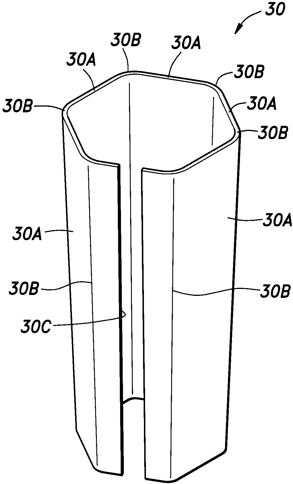
[0073] Figure 5 It is a perspective view showing the state before attachment of the cylindrical member 40 of 2nd Embodiment. In this embodiment, the structure and manufacturing method of the cylindrical member 40 differ from 1st Embodiment. Specifically, the cylindrical member 40 is obtained by processing a steel pipe having a circular or hexagonal cross-section into a tapered regular polygonal cross-section (regular hexagonal cross-section in the illustrated example) by pipe expansion or die forging. Metal cylinder, constructed without slit 30C ( figure 2 ) closed section shape.
[0074] When the base end side of the cylindric...
no. 3 approach 》
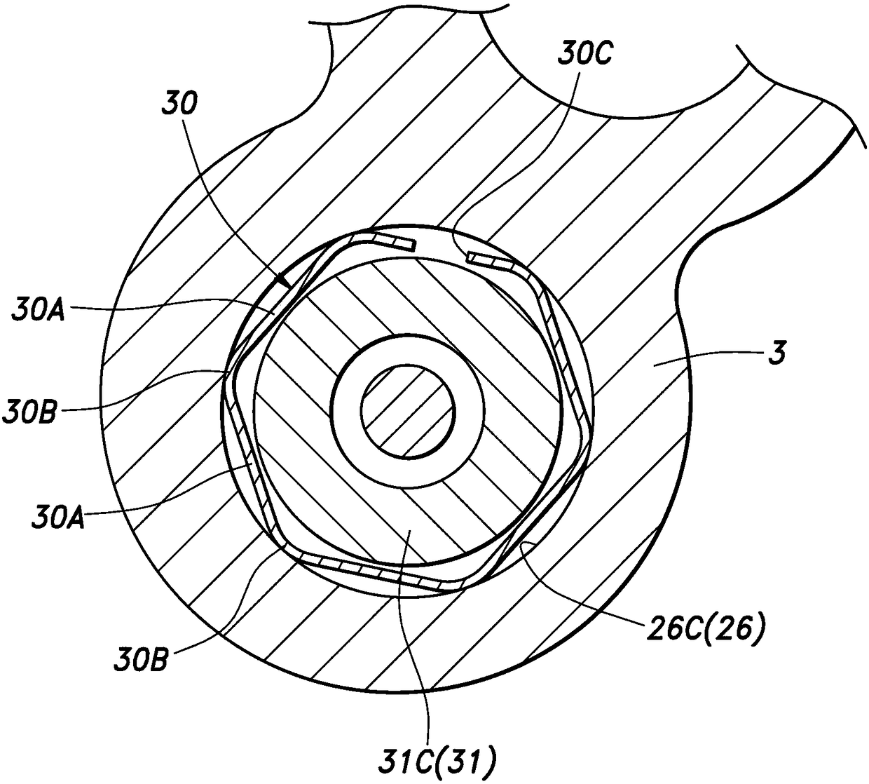
[0078] Next, refer to Figure 6 A third embodiment will be described. Figure 6 is equivalent to the tubular member 50 of the third embodiment Figure 4 An enlarged sectional view of the base end side of the main part. In the present embodiment, in a state before being inserted into the injector attachment hole 26 , the base end side of the cylindrical member 50 is curved so that the center of the width direction of each side portion 50A is convex inward as shown by a phantom line. A shape that is closer to a star than a regular hexagon.
[0079] Such as Figure 6 As shown, the base end side of the cylindrical member 50 is elastically deformed in such a manner that the maximum cross-sectional dimension of the outer profile is reduced when inserted into the injector mounting hole 26 . The elastic deformation of the proximal end side of the cylindrical member 50 is caused by bending deformation of the corner portion 50B that increases the radius of curvature of the corner po...
PUM
 Abstract
Description
Claims
Application Information
 - R&D Engineer
- R&D Manager
- IP Professional
- Industry Leading Data Capabilities
- Powerful AI technology
- Patent DNA Extraction
Browse by: Latest US Patents, China's latest patents, Technical Efficacy Thesaurus, Application Domain, Technology Topic.
© 2024 PatSnap. All rights reserved.Legal|Privacy policy|Modern Slavery Act Transparency Statement|Sitemap