Electric connection box

A technology for electrical connection boxes and circuit substrates, used in electrical components, cooling/ventilation/heating transformation, etc.

Inactive Publication Date: 2011-11-16
AUTONETWORKS TECH LTD +2
View PDF8 Cites 0 Cited by
  • Summary
  • Abstract
  • Description
  • Claims
  • Application Information

AI Technical Summary

Problems solved by technology

However, according to this method, since the air is only in contact with the surface of the bus bar, heat cannot be effectively transferred from the bus bar to the air, and it is difficult to sufficiently cool the bus bar

Method used


Image

  • Electric connection box
  • Electric connection box
  • Electric connection box

Examples


Embodiment Construction

[0034] Embodiments of the present invention will be specifically described below with reference to the drawings.

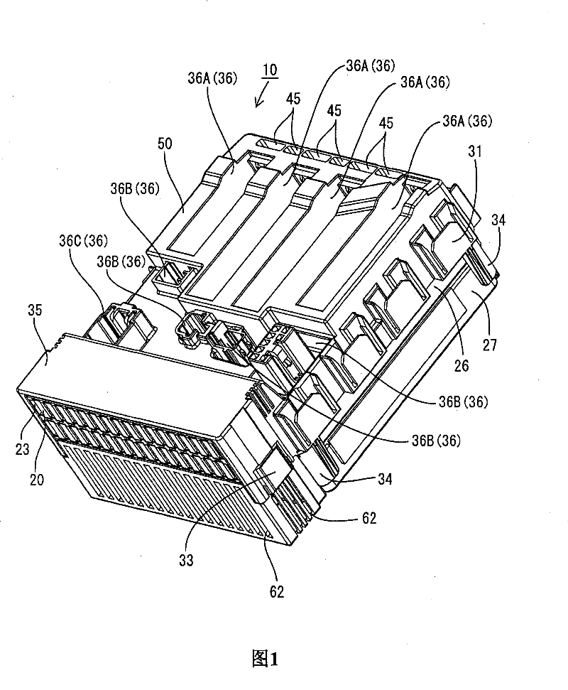
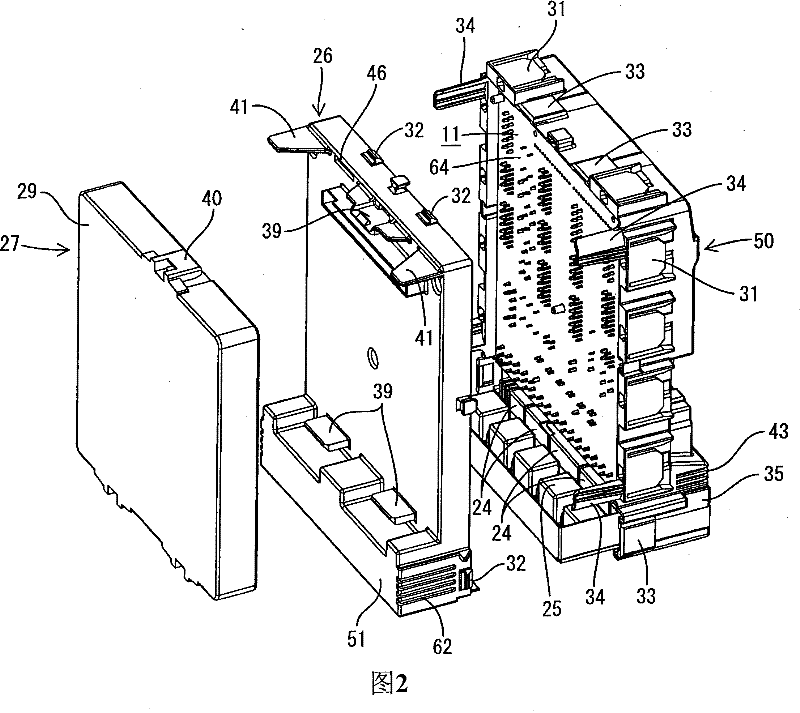
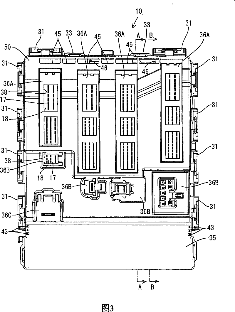
[0035] refer to Figure 1 to Figure 7 The first embodiment of the present invention will be described. The electrical junction box of this embodiment is installed between a battery (not shown) and vehicle electrical components (not shown) such as lamps and power windows, and controls the energization and de-energization of these vehicle electrical components. The electrical connection box is as Image 6 The shown vertical state is installed in the interior of a car (not shown) and used. In this electrical connection box, a circuit board 11 is accommodated in a flat case 10 .

[0036] (circuit board)

[0037] The circuit board 11 is substantially rectangular, and conductive paths (not shown) are formed on both sides thereof by printed wiring technology. In the circuit substrate 11, in Figure 7 On the surface on the middle right side (hereinafter referred to ...


PUM


Abstract

An electric connection box according to one aspect of the present invention can include conductive members on a circuit board, a case accommodating the circuit board, a ventilation path formed in the case and through which air can flow in a vertical direction, a suction port formed in the case to be in communication with the ventilation path, an exhaust port formed in the case to be in communication with the ventilation path, the exhaust port positioned above the suction port, cooled portions positioned on the conductive members and positioned in the ventilation path so as to allow air to flow in the vertical direction between conductive members, and heat generating components connected to the cooled portions of the conductive members.

Description

Technical field [0001] The invention involves an Electrical Connection Box formed in the shell. Background technique [0002] In the past, as an electric connection box, the electric connection box was recorded in patent literature 1 (Japan special opening 2005-295724).The electrical connection box, the relay module equipped with a relay was contained on the circuit substrate.When power -on to the above relay, heat generates heat from the relay.After the heat is dispersed in the shell, it diverts from the wall of the shell to the outside. [0003] In recent years, the high density of the electric connector is required.Therefore, the number of relays that contain the shells increase, and the heat from the relay is increasing.Furthermore, the miniaturization of the electric connector is required, and the volume in the shell is decreasing.Therefore, the heat accumulation from relays in the shell may make the shell high temperature.If the shell becomes high temperature, the performan...

Claims


Application Information

Patent Timeline
Patent Type & Authority Patents(China)
IPC IPC(8): H02G3/16H02G3/08H05K7/20
Inventor 清水达哉桥仓学西田太
Owner AUTONETWORKS TECH LTD
Why Eureka
Try Eureka