A once-through diffuse combustion tubular heating furnace system and burner

A tubular heating furnace and dispersion combustion technology, applied in the direction of gas fuel burners, burners, combustion methods, etc., can solve the problems of limited potential and inapplicability of tubular heating furnaces, achieve simple structure, suppress the formation of NOx, The effect of reducing the intensity of the reaction

Active Publication Date: 2017-06-06
EAST CHINA UNIV OF SCI & TECH
View PDF6 Cites 0 Cited by
  • Summary
  • Abstract
  • Description
  • Claims
  • Application Information

AI Technical Summary

Problems solved by technology

However, on the one hand, the thermal efficiency of the tubular heating furnace is generally higher than 90% due to the extreme recovery of flue gas waste heat through the heat exchanger to preheat the air, and the potential for energy saving of the tubular heating furnace using new technologies is limited; on the other hand, the tubular heating furnace The furnace structure of the heating furnace is obviously different from the heating furnace in the metallurgy, metal processing, and ceramic industries. The existing high-temperature and low-oxygen combustion technology is not suitable for tubular heating furnaces: therefore, high-temperature and low-oxygen combustion technology has not yet been applied to tubular heating furnaces.

Method used


Image

  • A once-through diffuse combustion tubular heating furnace system and burner
  • A once-through diffuse combustion tubular heating furnace system and burner
  • A once-through diffuse combustion tubular heating furnace system and burner

Examples


Embodiment 1

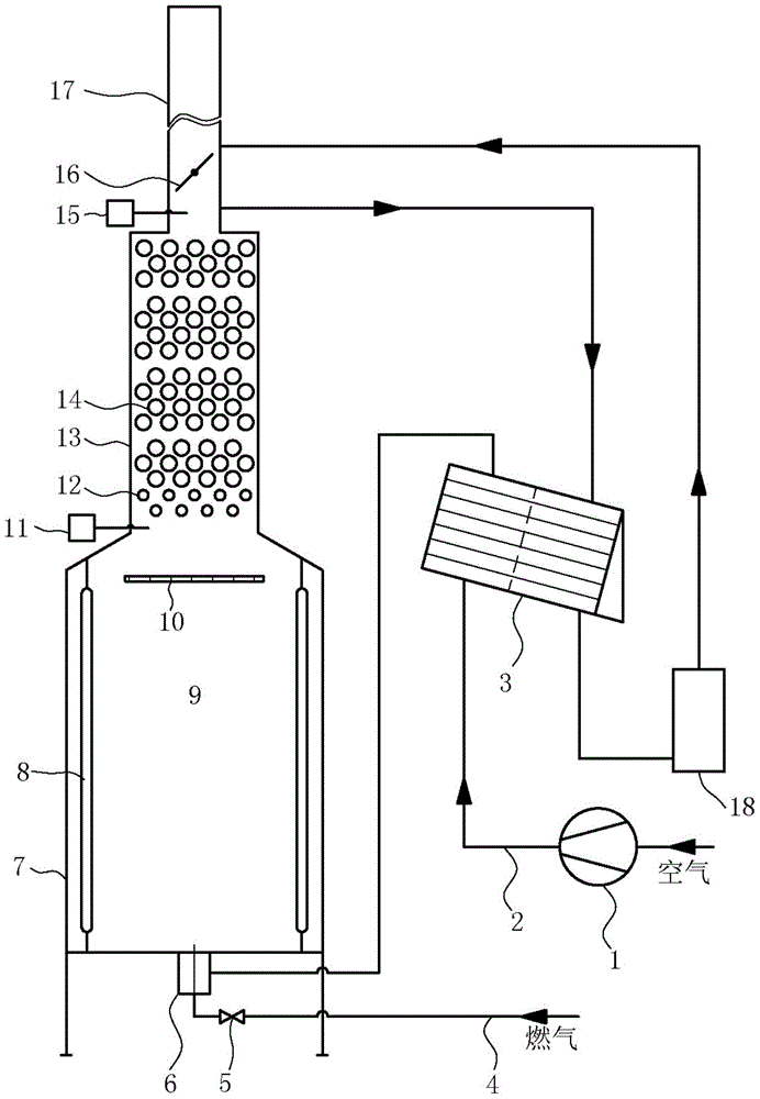
[0040] A direct-flow diffuse combustion tubular heating furnace. The cold air from the blower is heated by the air preheater and then injected into the radiation chamber through the burner. The gas from the gas pipe network is injected into the radiation chamber through the burner. The temperature of the radiation chamber is high. Due to the self-ignition temperature of the gas, hot air and gas entrain the combustion products in the radiation chamber, forming a strong backflow in the radiation chamber, and the jet velocity of the reactants is greater than the flame propagation speed of the gas combustion, so no visible luminous flame can be formed in the radiation chamber. The combustion of gas fills the entire radiant chamber, and the maximum temperature of the combustion process is less than 1700K, which effectively suppresses the formation of NOx; the reflector prevents the high-speed gas and hot air from forming a short circuit in the radiant chamber and directly enters the ...

Embodiment 2

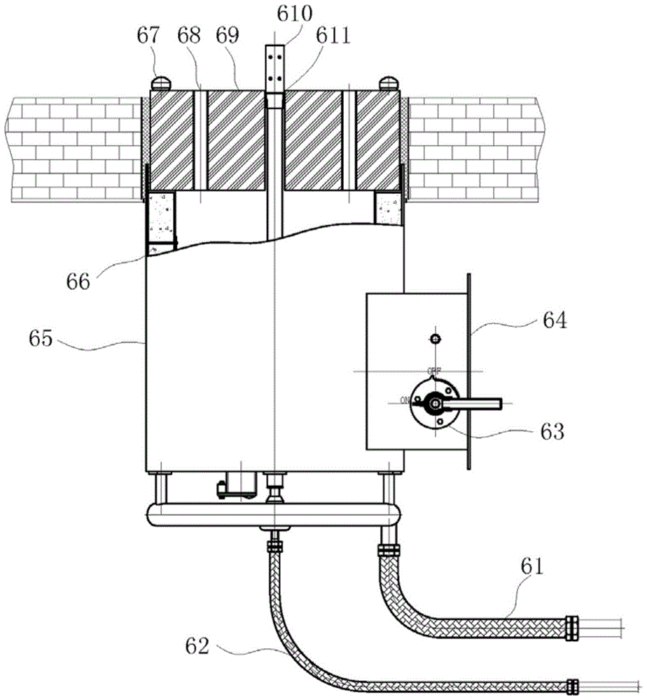
[0049] The tubular heating furnace system and burner structure of Embodiment 2 are consistent with Embodiment 1. With methane as the fuel gas, the excess air coefficient is 1.10, and the velocity field, temperature field and CO and NOx emissions of the diffuse combustion in the combustion chamber 9 of the 37.8MW tubular heating furnace are simulated and studied. The diameter of the combustion chamber 9 is 5400mm, and the height is 10000mm, the volume heat intensity of combustion chamber 9 is 165kW / m 3 , the speed at which methane is ejected from the gas gun 67 is 60m / s, the cold air is heated to 673K ​​by the air preheater 3, the speed at which the hot air is ejected from the air hole 68 is 120m / s, and the diameter of the reflecting plate 10 is 3430mm, It is 0.64 times of the diameter of the combustion chamber. With reference to the operating conditions of general refining and chemical tubular heating furnaces, the temperature of the wall surface of the combustion chamber 9 is...


PUM


Abstract

The invention relates to a straight-flow type dispersion combustion tubular heating furnace system and a combustor. Fuel gas and preheated air are injected into a combustion chamber of a radiation chamber by a high-speed fuel gas combustor; the temperature of a hearth is higher than spontaneous ignition temperature; the injection speed is greater than the flame spreading speed during combustion of the fuel gas, so that visible luminous flame cannot be formed; reaction of combustion is performed in the whole radiation chamber; heat distributed in the radiation chamber is uniform; the maximum temperature of a combustion process is smaller than 1700K; and NOx is restrained effectively. A reflecting plate is arranged on a downstream portion of the radiation chamber, the circumstance that the fuel gas and the hot air are in a short-circuiting state in the radiation chamber and directly enter a convection chamber can be avoided, backflow is formed on a downstream portion of the reflecting plate, standing time of smoke in the convection chamber is prolonged, and combustible ingredients such as CO can be sufficiently burnt out. The straight-flow type dispersion combustion tubular heating furnace system has the advantages of high combustion efficiency, ultra-low pollutant emission, uniform temperature field and the like. Moreover, the straight-flow type dispersion combustion tubular heating furnace system is suitable for building a new tubular heating furnace or modifying an old tubular heating furnace.

Description

[0001] 【Technical field】 [0002] The invention relates to the technical field of tubular heating furnaces in refining and chemical enterprises, in particular to a diffuse combustion tubular heating furnace and a burner thereof. [0003] 【Background technique】 [0004] Tube heating furnace is a process heating furnace commonly used in refining and chemical enterprises. In the combustion chamber surrounded by refractory materials, the heat released by fuel combustion heats the medium in the furnace tube to the required temperature to make it react or meet the requirements of subsequent processes. . The operation of the tubular heating furnace requires that the fuel is fully burned, the pollutants produced by the combustion are low, and the furnace tubes in the furnace are heated evenly, so as to realize the high efficiency, environmental protection, safety and long-term operation of the tubular heating furnace. [0005] At present, most of the tubular heating furnaces in refini...

Claims


Application Information

Patent Timeline
Patent Type & Authority Patents(China)
IPC IPC(8): F23D14/62F23D14/46F23N5/00
CPCF23D14/12F23D14/46F23D14/66F23N5/003F23N5/006Y02E20/34
Inventor 徐宏刘波程子非王元华张莉范永坚
Owner EAST CHINA UNIV OF SCI & TECH
Why Eureka
Try Eureka