A low-nitrogen combustion system for a regenerative heating furnace and its working method

A low-nitrogen combustion and heating furnace technology, applied in the field of heating furnace combustion, can solve the problems of ineffective recycling, high NOx emissions, and small firepower, so as to avoid local high temperature of the flame, save energy, and reduce heat loss rate effect

Active Publication Date: 2022-02-22
SHANDONG YIRAN ENVIRONMENTAL PROTECTION TECH CO LTD
View PDF7 Cites 0 Cited by
  • Summary
  • Abstract
  • Description
  • Claims
  • Application Information

AI Technical Summary

Problems solved by technology

Since the single regenerative energy-saving burner only pre-storages energy-saving combustion for the combustion-supporting air, and does not adopt low-nitrogen emission reduction combustion and natural gas pre-storage and energy-saving combustion, the sensible heat of the high-temperature flue gas, which accounts for a large proportion, cannot be obtained. Effective recycling, high NOx emissions
[0005] In terms of thermal automatic control technology, there is still a common problem of single firepower adjustment, and the temperature adjustment in the heat preservation stage can only be realized by turning on and off the gas. Due to the large firepower and the inability to adjust the firepower to become smaller, a large waste of gas is caused.
When the heating furnace, especially the intermittent heating furnace, is shut down, the air enters the high-temperature furnace through the combustion-supporting air blower pipe, and then is discharged through the smoke exhaust fan pipe, so that a part of the sensible heat of the high-temperature furnace is released from the furnace and enters the atmosphere through the air carrier, causing a large number of physical heat loss

Method used


Image

  • A low-nitrogen combustion system for a regenerative heating furnace and its working method

Examples


Embodiment

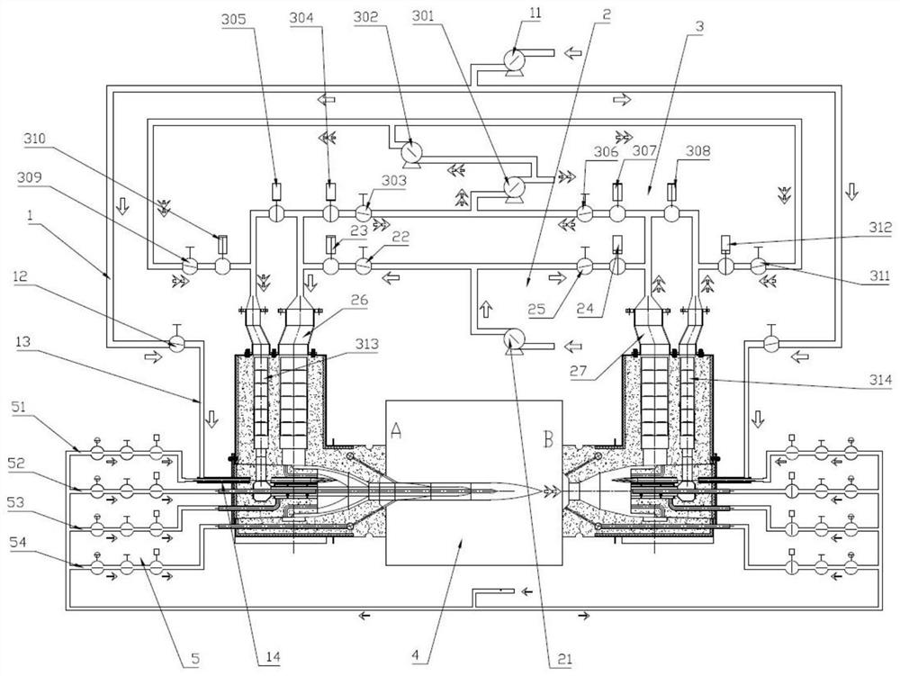
[0040] see figure 1 , the low-nitrogen combustion system of the regenerative heating furnace in this embodiment includes the furnace 4 and the burners A and B on both sides of the furnace 4. The A and the burners are double regenerators, respectively, and the flue gas The regenerator and the air regenerator, and the flue gas regenerator is located behind the air regenerator, away from the side of the furnace 4, and plays the role of thermal insulation for the burner box, so that the burner box surface temperature Reduced, with energy-saving effect. In addition, the system also includes an ignition system 1 , an air supply system 2 , a flue gas circulation system 3 and a gas supply system 5 .

[0041] The ignition system 1 includes a high-pressure vortex air pump 11, a first manual regulating valve 12, an air supply pipeline 13 and an ignition pipeline 14. One end of the air supply pipeline 13 is connected to the high-pressure vortex air pump 11, and the other end is connected...


PUM


Abstract

A low-nitrogen combustion system for a regenerative heating furnace, including a furnace and burners A and B on both sides of the furnace, and also includes an ignition system, an air supply system, a flue gas circulation system and a gas supply system; the ignition system includes Air induction device and ignition pipe; said air supply system includes air induction device, air supply pipe and the air regenerator on the top of burner A and burner B; said flue gas circulation system includes induced draft fan, flue gas pipe and The flue gas regenerator on the upper part of nozzle A and burner B, two flue gas pipes are connected between the two flue gas regenerators, and an induced draft fan is connected between the two flue gas pipes; the gas supply system includes four Level gas pipelines are respectively the first low-pressure gas pipeline, high-pressure gas pipeline, second low-pressure gas pipeline and medium-pressure gas pipeline, which are connected to the injection port inside the burner and the furnace in layers. It can effectively suppress the local high temperature of the flame caused by concentrated heating, let the combustion temperature of the burner release in layers, and further avoid the local high temperature of the flame.

Description

technical field [0001] The invention relates to the technical field of heating furnace combustion, in particular to a regenerative heating furnace low-nitrogen combustion system and a working method thereof. Background technique [0002] The energy consumption of industrial furnaces in my country accounts for about 25% of the total energy consumption in the country, and the energy consumption of heating furnaces accounts for more than 90% of the total energy consumption of industrial furnaces. It can be seen that heating furnaces occupy a pivotal position in my country's manufacturing field. However, the energy utilization rate of industrial furnaces in my country has always been low. Taking the continuous heating furnace with the highest thermal efficiency as an example, it is only 30% to 40%. The average thermal efficiency of fuel furnaces in developed countries in the world is about 50%. [0003] There is still great potential for energy saving and emission reduction of ...

Claims


Application Information

Patent Timeline
Patent Type & Authority Patents(China)
IPC IPC(8): F23D14/02F23D14/46F23D14/60F23D14/62F23D14/78
CPCF23D14/02F23D14/46F23D14/60F23D14/62F23D14/78
Inventor 于涛张晓
Owner SHANDONG YIRAN ENVIRONMENTAL PROTECTION TECH CO LTD
Why Eureka
Try Eureka