Fitting
A technology of pipe joints and flexible pipes, applied in the field of pipe joints, can solve problems such as long time
- Summary
- Abstract
- Description
- Claims
- Application Information
AI Technical Summary
Problems solved by technology
Method used
Image


Examples
no. 1 approach
[0023] The pipe joint according to the first embodiment of the present invention has a structure in which sealing between the pipe joint and the flexible pipe joint is possible by performing an inserting step of inserting a flexible pipe into the pipe joint and a locking step of coupling the inserted flexible pipe to the pipe joint. A flexible tube is combined in a state between the sex tubes.
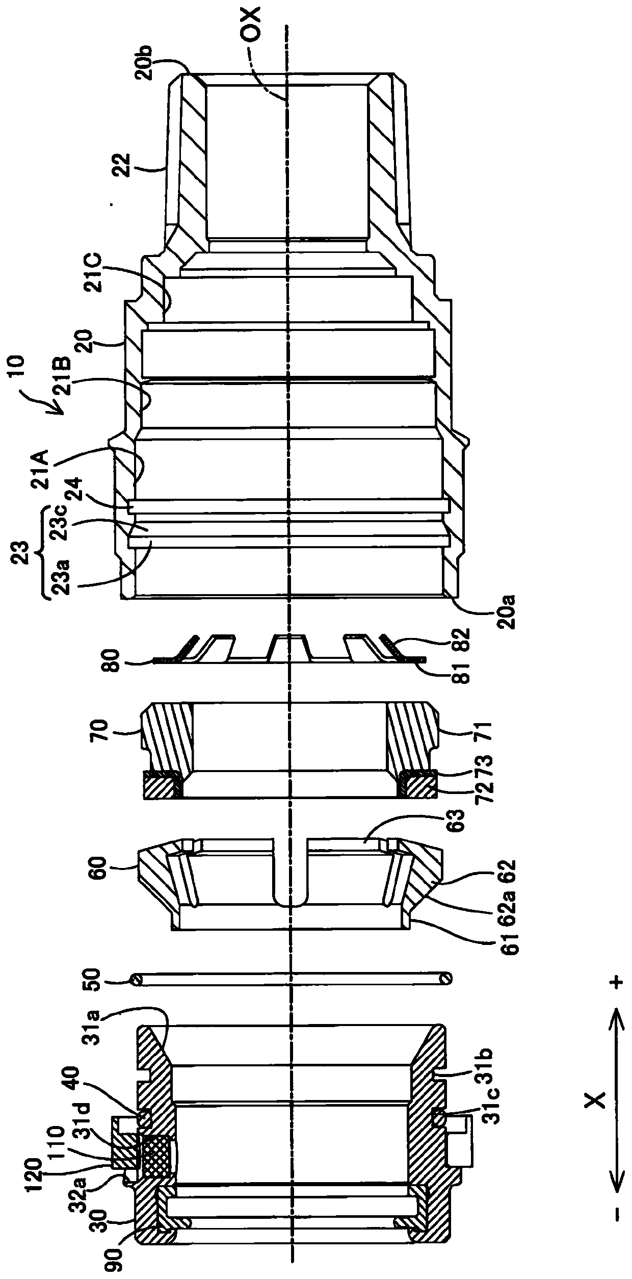
[0024] figure 1 It is a partial sectional side view showing the state after the insertion process of the pipe joint 10 according to the first embodiment of the present invention, figure 2 It is a partial cross-sectional side view showing the state of the pipe joint 10 after the locking process. image 3 It is a cross-sectional view showing a disassembled state of the pipe joint 10 . exist Figure 1 ~ Figure 3 Here, the X direction is a direction (axial direction) along the central axis OX of the pipe joint 10 . Hereinafter, the direction on the right side in the figure of the X di...
no. 2 approach
[0047] Figure 8 It is a top view of the periphery of the push nut 230 included in the pipe joint according to the second embodiment of the present invention. Figure 8 is the same as in the first embodiment Figure 7 The corresponding figure shows the periphery of the push nut 230 in the state after the locking process. The pipe joint in the second embodiment differs from the pipe joint 10 in the first embodiment in that the position of the communication hole 231d in which the selectively permeable member 110 is fitted is different. The other structures of the pipe joint in the second embodiment are the same as those of the pipe joint 10 in the first embodiment, so regarding the same constituent elements, Figure 8 marked with Figure 7 The same reference numerals are used and descriptions thereof are omitted.
[0048] The communication hole 231d is located more than the communication hole 31d in the first embodiment (refer to Figure 5 ) on the +X direction side, in the...
no. 3 approach
[0051] Figure 9 It is a top view of the periphery of the push nut 330 included in the pipe joint according to the third embodiment of the present invention. Figure 9 is the same as in the second embodiment Figure 8 The corresponding figure shows the periphery of the push nut 330 in the state after the locking process. The pipe joint in the third embodiment differs from the pipe joint in the second embodiment in that it does not have a spot facing portion, and a diamond-shaped mark 332 a is attached to the position where the spot facing portion is formed in the second embodiment. Since other structures of the pipe joint in the third embodiment are the same as those of the pipe joint in the second embodiment, regarding the same constituent elements, in Figure 9 marked with Figure 8 The same reference numerals are used and descriptions thereof are omitted. The marks 332 may be formed in other shapes such as a triangle or an arrow instead of a rhombus. Mark 332 correspon...
PUM
 Abstract
Description
Claims
Application Information
 - R&D
- Intellectual Property
- Life Sciences
- Materials
- Tech Scout
- Unparalleled Data Quality
- Higher Quality Content
- 60% Fewer Hallucinations
Browse by: Latest US Patents, China's latest patents, Technical Efficacy Thesaurus, Application Domain, Technology Topic, Popular Technical Reports.
© 2025 PatSnap. All rights reserved.Legal|Privacy policy|Modern Slavery Act Transparency Statement|Sitemap|About US| Contact US: help@patsnap.com