Apparatus and method for monitoring carbon dioxide flux of soil in aeration zone of gas injection oil displacing oil well
A carbon dioxide and monitoring device technology, which is applied in measuring devices, sampling devices, sampling, etc., can solve the problems of inaccurate flux measurement, achieve high frequency, realize continuous background correction and dynamic air pressure balance, and achieve high monitoring accuracy.
- Summary
- Abstract
- Description
- Claims
- Application Information
AI Technical Summary
Problems solved by technology
Method used
Image
Examples
Embodiment 1
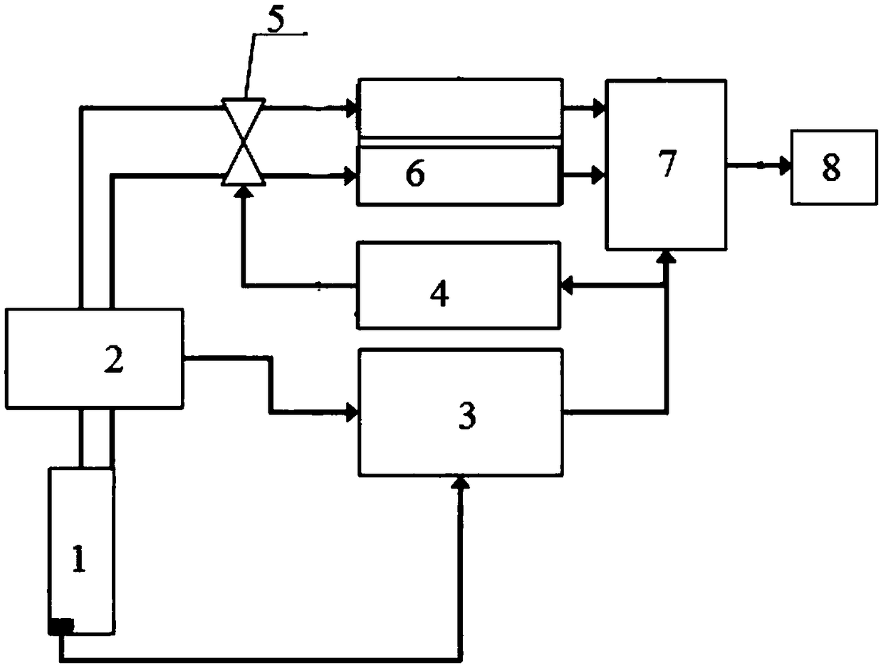
[0031] This embodiment provides a figure 1 The gas injection flooding wellsite soil carbon dioxide flux monitoring device in the aerated zone shown includes a gas production column 1 connected in sequence, a gas parameter monitor 2, a gas production pump 5, and an infrared gas analyzer 6. The infrared gas analyzer 6 Electrically connected to a data transmission module 7, the gas extraction pump 5 is electrically connected to an air extraction pump action controller 4, and the gas extraction pump action controller 4 is electrically connected to the data transmission module 7;
[0032] Described gas collection column 1 is provided with temperature sensor 1-2, soil moisture sensor 1-1 and pressure balance valve 1-9, and the collection of described gas collection column 1 includes the collection of sample gas and the collection of reference air, so The gas parameter monitor 2, the temperature sensor 1-2 and the soil moisture sensor 1-1 are all electrically connected to a recording...
Embodiment 2
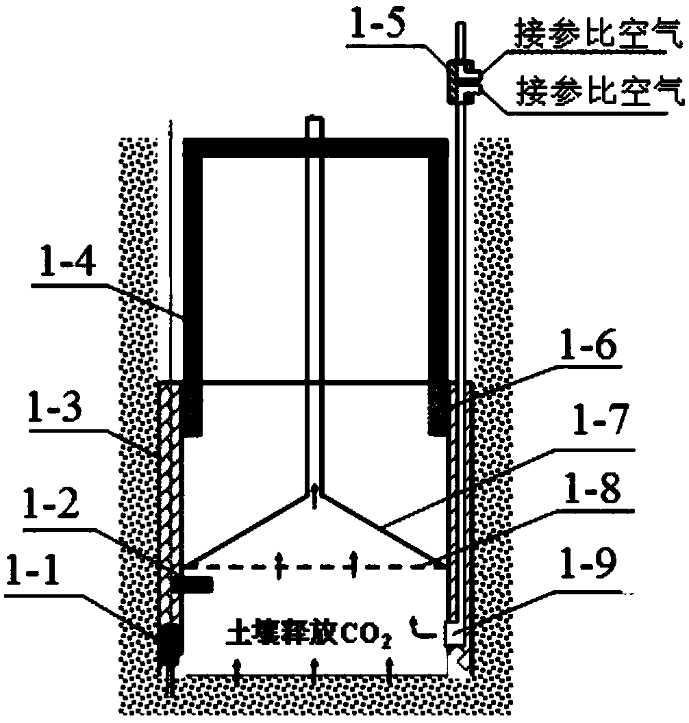
[0036]On the basis of Embodiment 1, this embodiment provides a monitoring device for soil carbon dioxide flux in the aerated zone of the gas injection flooding well site, and the gas production column 1 includes a depth positioning rod 1-4 and a gas production box 1-3 , gas collection cover 1-7, pressure balance valve 1-9, temperature sensor, soil moisture sensor and emptying valve 1-5, the upper end of the gas collection box 1-3 is connected and sealed with the depth positioning rod 1-4, the The lower end of the gas collection box 1-3 is open, the gas collection hood 1-7 is arranged in the gas collection box 1-3, and the straight pipe on the upper part of the gas collection hood 1-7 passes through the depth positioning rod 1-4 and the gas Parameter monitor 2 connection;
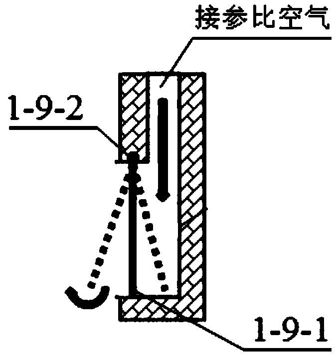
[0037] The temperature sensor 1-2, the soil moisture sensor 1-1 and the pressure balance valve 1-9 are all arranged in the gas collection box 1-3, and the pressure balance valve 1-9 is connected to the empty...
Embodiment 3
[0043] On the basis of the gas injection flooding wellsite soil carbon dioxide flux monitoring device in Example 1, this embodiment provides a soil carbon dioxide flux monitoring method, which includes the following steps:
[0044] Step 1) Carry out soil drilling at the monitoring point, insert the gas extraction column 1 after reaching the target depth, and connect all components;
[0045] Step 2) Turn on the gas sampling pump 5, and keep the sample gas collection flow consistent with the reference air collection flow, and monitor the CO in the sample gas by the infrared gas analyzer 6. 2 Concentration and reference air CO 2 Concentration, and pass to data transmission module 7;
[0046] Step 3) The sample gas and reference air flow rate, air pressure and temperature sensor 1-2 detected by the gas parameter monitor 2, and the soil moisture content detected by the soil moisture sensor 1-1 are all recorded in the recording module 3, and used The data transmission module 7 is ...
PUM
| Property | Measurement | Unit |
|---|---|---|
| Diameter | aaaaa | aaaaa |
| Thickness | aaaaa | aaaaa |
Abstract
Description
Claims
Application Information
 - R&D
- Intellectual Property
- Life Sciences
- Materials
- Tech Scout
- Unparalleled Data Quality
- Higher Quality Content
- 60% Fewer Hallucinations
Browse by: Latest US Patents, China's latest patents, Technical Efficacy Thesaurus, Application Domain, Technology Topic, Popular Technical Reports.
© 2025 PatSnap. All rights reserved.Legal|Privacy policy|Modern Slavery Act Transparency Statement|Sitemap|About US| Contact US: help@patsnap.com


